Horn temperature testing system and method based on phase change measurement

A phase change and test system technology, applied in the direction of electrical components, etc., can solve the problems of area consumption and power consumption, power amplifiers and filters, occupying a large area, and occupying a large area, so as to reduce complexity, occupy a small area, The effect of simple structure

Active Publication Date: 2020-12-22
SHANGHAI FOURSEMI SEMICON CO LTD
View PDF12 Cites 0 Cited by
  • Summary
  • Abstract
  • Description
  • Claims
  • Application Information

AI Technical Summary

Problems solved by technology

[0029] (1) Due to the small current signal, a high-precision ADC is required; depending on the structure of the selected ADC, power amplifiers and filters that consume area and power consumption may also be required;
[0030] (2) Division operation is required, and the circuit is complex;
[0031] (3) High-order filters are required, which occupy a large area
The device and method still do not solve the above problems, and have the defects of complex circuit, large occupied area, and large power consumption

Method used


Image

  • Horn temperature testing system and method based on phase change measurement
  • Horn temperature testing system and method based on phase change measurement
  • Horn temperature testing system and method based on phase change measurement

Examples


Embodiment 1

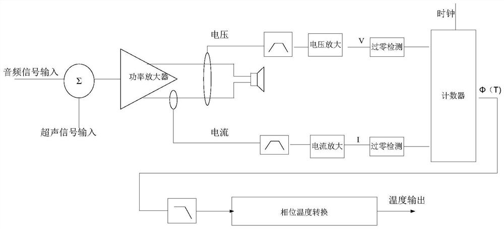
[0080] This embodiment provides a horn temperature testing system based on phase change measurement, such as figure 2 As shown, it includes: an adder, a power amplifier connected to the output of the adder, a voltage processing component and a current processing component connected to the output of the power amplifier and arranged in parallel, a counter connected to the output of the voltage processing component and the current processing component, connected to A phase temperature converter at the output end of the counter; the voltage processing component and the current processing component both include a band-pass filter, an amplification circuit and a zero-crossing detection circuit arranged in sequence;

[0081] in:

[0082] The adder adds the input audio signal and the ultrasonic signal used for testing to obtain a sum signal, and outputs it to the power amplifier;

[0083] The power amplifier amplifies the obtained sum signal, and outputs a voltage signal and a curre...

Embodiment 2

[0119] This embodiment provides a horn temperature testing method based on phase change measurement, using the horn temperature testing system based on phase change measurement provided in Embodiment 1, such as Figure 4 shown, including the following steps:

[0120] Step S1, adding the input audio signal and the ultrasonic signal used for testing to obtain a sum signal;

[0121] Step S2, amplifying the sum signal, and outputting a voltage signal and a current signal to drive a load;

[0122] Step S3:

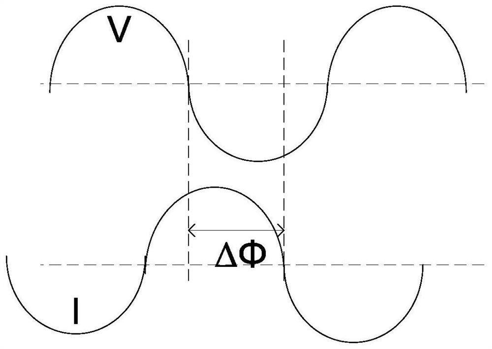
[0123] - extract the ultrasonic voltage signal in the output voltage signal, amplify the ultrasonic voltage signal, and perform zero-crossing detection on the amplified ultrasonic voltage signal to obtain the voltage zero-crossing moment;

[0124] - Extract the ultrasonic current signal in the output current signal, amplify the ultrasonic current signal, and perform zero-crossing detection on the amplified ultrasonic current signal to obtain the current zero-crossing moment; ...


PUM


Abstract

The invention provides a horn temperature test system based on phase change measurement. The horn temperature test system comprises an adder, a power amplifier connected to the output of the adder, avoltage processing component and a current processing component connected to the output end of the power amplifier and arranged in parallel, a counter connected to the output ends of the voltage processing component and the current processing component, a phase temperature converter connected to the output end of the counter; wherein the voltage processing component and the current processing component each include a band pass filter, an amplifying circuit, and a zero crossing detecting circuit which are successively disposed. Further, a horn temperature test method based on phase change measurement is provided. The horn temperature test system and method based on phase change measurement provided by the invention can be realized only by a few components, and have the advantages of simplestructure, small occupied area and low power consumption.

Description

technical field [0001] The invention relates to the technical field of horn manufacturing, in particular to a horn temperature testing system and method based on phase change measurement. Background technique [0002] The working process of the horn is the process of converting electrical energy into sound energy; during the working process of the horn, its coil will generate heat, and if the heat cannot be dissipated in time, high temperature will be generated. The coil and the diaphragm are physically bonded together, and if the coil temperature is too high, the diaphragm will be damaged, causing distortion or even permanent damage to the speaker. [0003] Therefore, during the working process of the horn, it is necessary to monitor the temperature of the horn coil. [0004] In the prior art, the impedance-based measurement method is mostly used. The measuring principle of this impedance-based measurement method is: [0005] The impedance curve of the speaker of the mob...

Claims


Application Information

Patent Timeline
Patent Type & Authority Patents(China)
IPC IPC(8): H04R29/00
CPCH04R29/001
Inventor 刘伟吉
Owner SHANGHAI FOURSEMI SEMICON CO LTD
Why Eureka
Try Eureka