
Dynamoelectric machine having a thermosiphon

A technology of electric motors and hollow shafts, applied in the field of hollow shafts, to achieve stable air tightness, improve efficiency, and improve efficiency

Active Publication Date: 2019-01-15
SIEMENS AG
View PDF3 Cites 0 Cited by
  • Summary
  • Abstract
  • Description
  • Claims
  • Application Information

AI Technical Summary

Problems solved by technology

[0004] The disadvantage here is that, for recooling, correspondingly sized recooling surfaces must be provided in order to maintain sufficient cooling of the rotor

Method used


Image

  • Dynamoelectric machine having a thermosiphon
  • Dynamoelectric machine having a thermosiphon
  • Dynamoelectric machine having a thermosiphon

Examples


Embodiment Construction

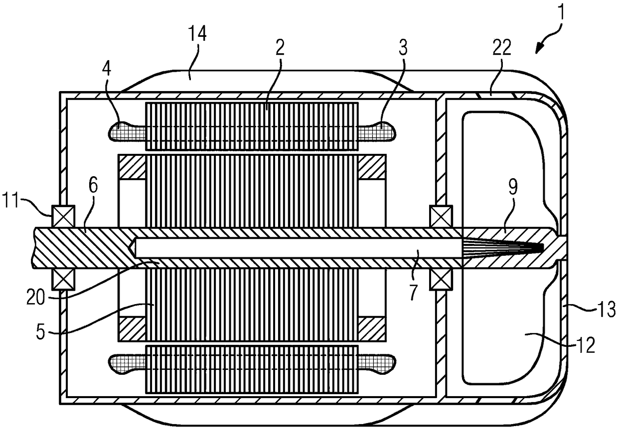
[0033] figure 1 A rotary electric motor 1 is shown having a stator 2 and a rotor 5 . In this embodiment, the rotor 5 is designed as a cage rotor, but it can also be a permanently excited rotor, a rotor of a reluctance machine or a rotor with a winding system.

[0034] The rotor 5 is connected in a rotationally fixed manner to the hollow shaft 6 , wherein the hollow shaft 8 is mounted in bearings 11 . A torsionally fixed connection is understood here to be a torque-transmitting connection, for example a heat shrink connection or a keyed connection or another hub connection between the laminated core of the rotor 5 and the hollow shaft 8 . The housing of the motor 1 carries the bearing housing. On the radially outer housing of the stator 2 there are axially extending cooling ribs 14 which guide the cooling air flow generated by the fan 12 along the housing. In this case, the fan 12 is mounted in a fan hood 13 , which optionally has an opening 22 .

[0035] In this embodiment...


PUM


Abstract

The invention relates to a hollow shaft (6), which forms a closed-off cavity, which has, axially, at least an evaporator zone (8) and a condenser zone (9), wherein at least the condenser zone (9) hasa microscale structure (16), and wherein the evaporator zone (8) and the condenser zone (9) can be connected in a thermally conductive manner to the respective surrounding elements thereof. The invention further relates to a method for producing such a hollow shaft (6), and to the use in dynamoelectric machines (1).

Description

technical field [0001] The invention relates to a hollow shaft forming a closed cavity with at least one evaporation zone and a condensation zone in the axial direction, the invention relates to a method for producing such a hollow shaft and its use in electric motors in the application. Background technique [0002] Rotary electrical machines and also their rotors are usually cooled by means of a cooling air flow caused by axial ventilation. However, such a cooling air flow is not sufficient if the thermal load on the rotor is high. A hollow shaft is subsequently provided here, in which a cooling medium is contained, which draws off the heat of the rotor and dissipates it axially to the outside via the shaft. [0003] Thus, for example, DE 10 2009 051 114 A1 shows an electric machine with a rotor, wherein the rotor has a hollow shaft, and wherein a closed cavity is provided by means of the hollow shaft, wherein the closed cavity is provided for receiving a coolant, Where...

Claims


Application Information

Patent Timeline
Patent Type & Authority Applications(China)
IPC IPC(8): H02K9/20
CPCH02K15/00H02K9/225H02K7/003H02K9/06
Inventor 克劳斯·比特纳克劳斯·基希纳马蒂亚斯·瓦尔穆特
Owner SIEMENS AG
Learn More