Bottom filter type landing fish tank

A filter type, fish tank technology, applied in the direction of filter treatment, fish farming, multi-stage water treatment, etc., can solve problems such as uncontrollable food intake

Active Publication Date: 2019-01-18
芜湖乐佳自动化机械有限公司
View PDF7 Cites 2 Cited by
  • Summary
  • Abstract
  • Description
  • Claims
  • Application Information

AI Technical Summary

Problems solved by technology

[0003] In the feeding process of the above-mentioned patent, the dry fish food is directly put into the fish tank. When the fish eat the dry fish food, the fish food will absorb water and expand, so that the fish will be stretched by the fish food; and only one kind of fish food can be provided. Eating, unable to control the amount of food eaten at one time

Method used


Image

  • Bottom filter type landing fish tank
  • Bottom filter type landing fish tank
  • Bottom filter type landing fish tank

Examples


Embodiment 1

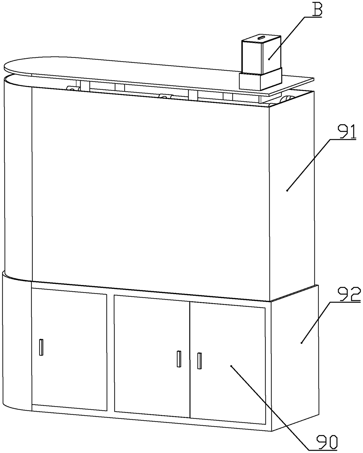
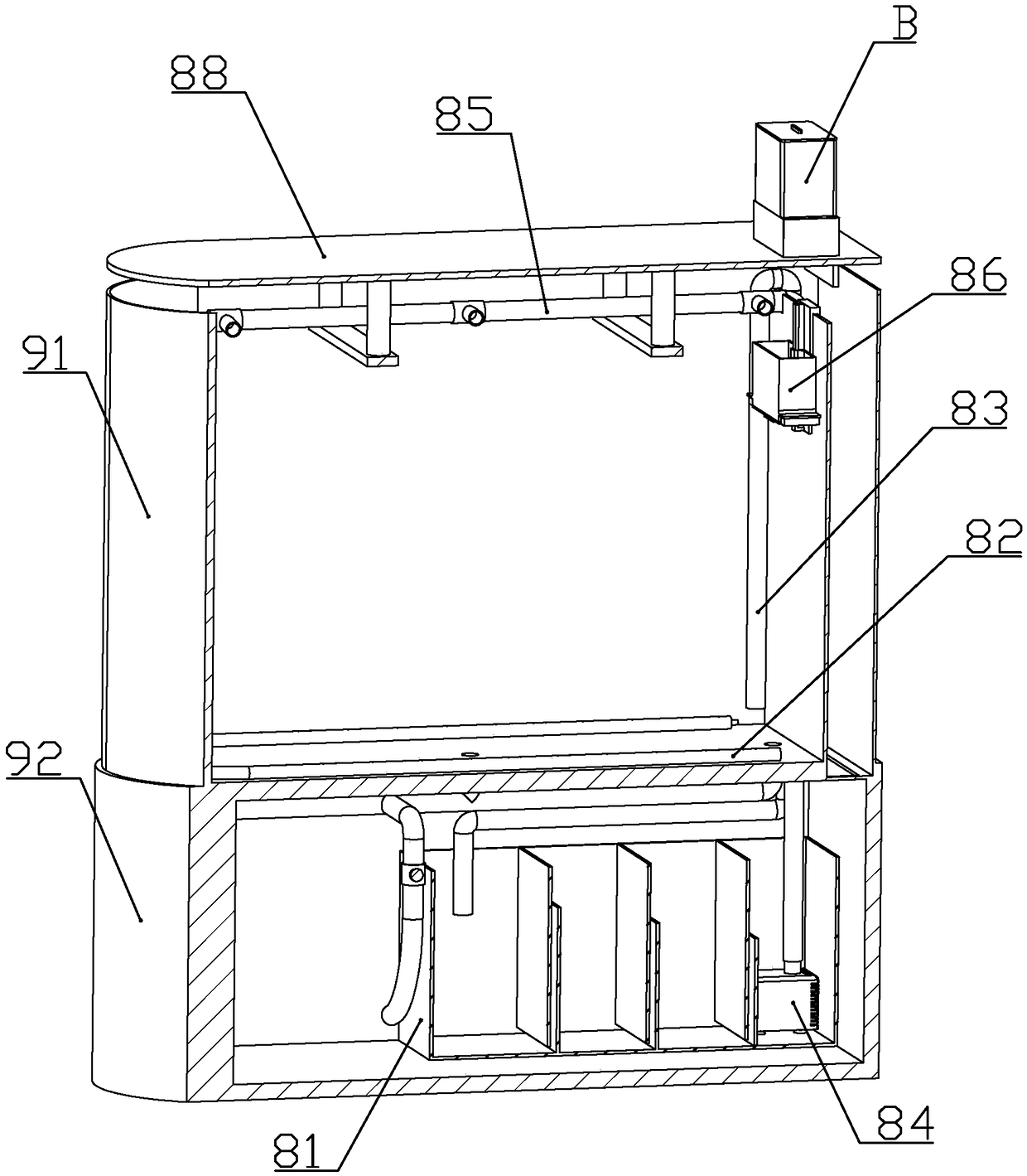
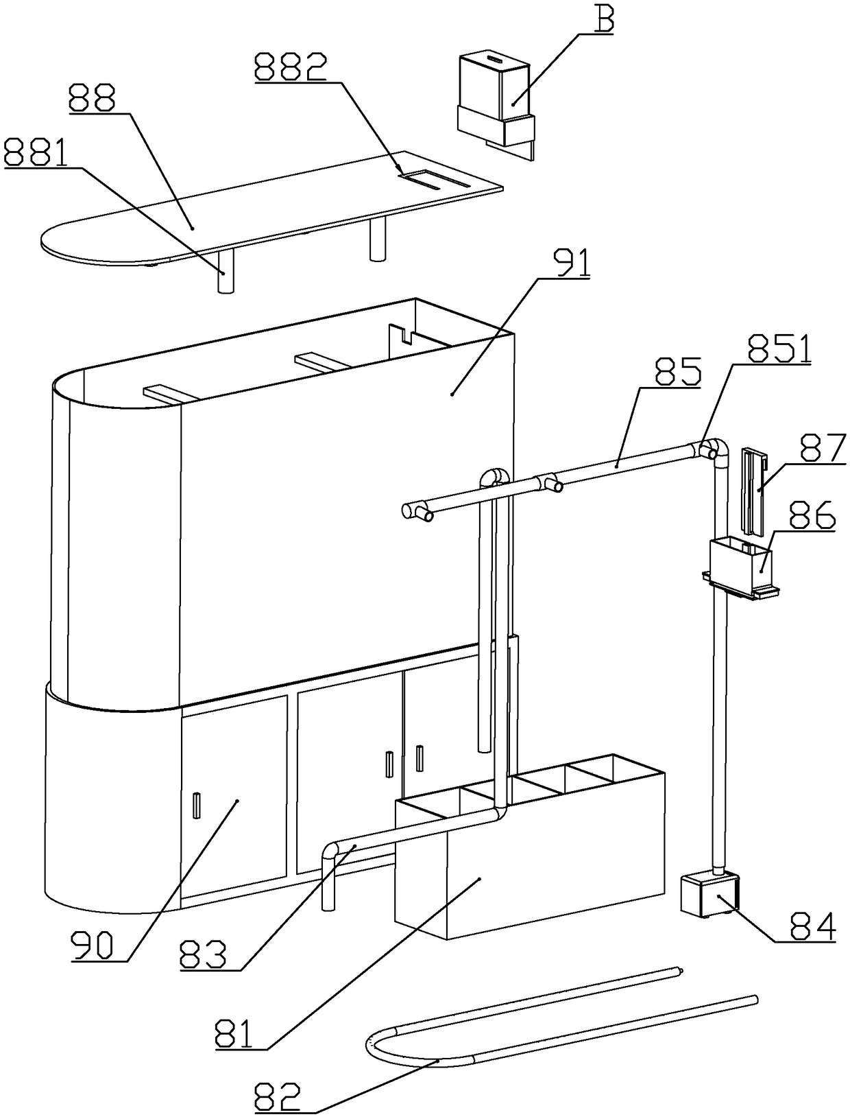
[0070] according to Figure 1 to Figure 18 As shown, a bottom filter floor fish tank described in this embodiment includes a cabinet body 92, and a cylinder body 91 fixedly installed on the upper end of the cabinet body; the upper end of the cylinder body is detachably connected with a feeder for feeding fish Device B; a filter box 81 for filtering the water in the cylinder is installed in the cabinet; a siphon 83 is provided between the cylinder and the filter box to pump the water in the cylinder into the filter box; A water pump 84 that pumps filtered water into the cylinder body is installed.

[0071] The cylinder body is quadrilateral as a whole, one short side wall of the cylinder body is semicircular, and the overall shape of the cabinet body is consistent with the cylinder body. A plurality of cabinet doors 90 are rotatably connected to the front end of the cabinet body.

[0072] The lower end of the cylinder is connected with a blowdown pipe 93 communicating with th...

Embodiment 2

[0163] The difference between this embodiment and Embodiment 1 is that the upper end of the valve plate is fixedly connected with a sealing gasket on one side of each material port; when the moving head is against the first sliding wall, the sealing gasket and the blanking The mouth is sealed against each other, so that the material storage chamber is in a closed environment.

[0164] When the controller controls the air pump to pump air in the storage chamber, the storage chamber can be evacuated, so that fish food can be stored better.

[0165] With the operation of the air pump, the air pressure in the material storage chamber decreases, so that the sealing piston moves downward, and always touches the upper end of the fish food. When performing the next air pumping work, it is only necessary to pump out the air below the sealing piston in the material storage chamber. That is, the extraction amount of air is reduced, and the workload of the air pump is reduced.


PUM

PropertyMeasurementUnit
thicknessaaaaaaaaaa

Abstract

The invention discloses a bottom filter type landing fish tank. The tank comprises a cabinet body and a cylinder body; a feeder for placing fish foods is connected with the upper end of the cylinder body; a filter box for filtering water in the cylinder body is installed in the cabinet body; a water pump which pumps the filtered water into the cylinder body is installed in the filter box. The inner wall of the cylinder body is slidably connected to a bubble tank floating on the water surface directly under the feeder; the lower end of the bubble tank is rotatably connected with a baffle plate;the lower end of the baffle plate is fixedly connected with a baffle plate float. A spray pipe communicated with the water pump is fixedly connected inside the cylinder body; a plurality of water spray joints are connected to the spray pipe; a water spray port of one water spray joint near the bubble tank faces the upper end of the bubble tank. A motor for controlling the discharge of the feederis installed in the feeder. Before the feeder discharges, a controller controls the water pump to operate at the first power; after the feeder discharges, the controller controls the water pump to operate at the second power after the set soaking time. By controlling the operation of the water pump, filtering the water in the cylinder body is achieved, and the fish foods in the bubble tank are discharged into the cylinder body.

Description

technical field [0001] The invention belongs to the technical field of fish tanks, and in particular relates to a floor-standing fish tank with bottom filtration. Background technique [0002] The Chinese patent document whose document number is CN207589883U discloses a fish tank for intelligent automatic feeding. A discharge cylinder is provided; a main shaft is arranged in the discharge cylinder; a discharge impeller is arranged on the main shaft and is located in each discharge cylinder; gears and racks are arranged at both ends of the main shaft; There is a screw sleeve in the middle of the lower end of the feeding hopper, and a screw is installed in the screw sleeve; a motor is installed at one end of the screw; the motor is connected to the controller; a humidity sensor and a heating tube are installed in the feeding hopper; Waist baffle in the shape of a waist triangle; the width of the bottom surface of the baffle is greater than the width of the discharge barrel. ...

Claims


Application Information

Patent Timeline
Patent Type & Authority Applications(China)
IPC IPC(8): A01K63/00A01K63/04A01K61/80C02F9/14
CPCA01K61/80A01K63/003A01K63/042A01K63/045C02F1/001C02F3/34C02F2301/08Y02A40/81
Inventor 麻景峰
Owner 芜湖乐佳自动化机械有限公司
Why Eureka
Try Eureka