Supercharge Your Innovation With Domain-Expert AI Agents!

Special bag cage for filtering materials

A special-shaped, filter material technology, applied in the direction of filtration separation, gravity filter, fixed filter element filter, etc., can solve the problems of easy blockage of the discharge port and poor filtering effect, and achieve better results

Inactive Publication Date: 2019-01-18
JIANGSU FUSHENG ENVIRONMENTAL PROTECTION GROUP
View PDF4 Cites 0 Cited by
  • Summary
  • Abstract
  • Description
  • Claims
  • Application Information

AI Technical Summary

Problems solved by technology

[0003] The purpose of the present invention is to provide a kind of filter material in order to solve the problem that the above-mentioned existing bag cage used for filter material has poor filtering effect during use, and the defect that the bag cage is easy to block when discharging waste materials. With shaped bag cage

Method used


Image

  • Special bag cage for filtering materials
  • Special bag cage for filtering materials

Examples


Embodiment 1

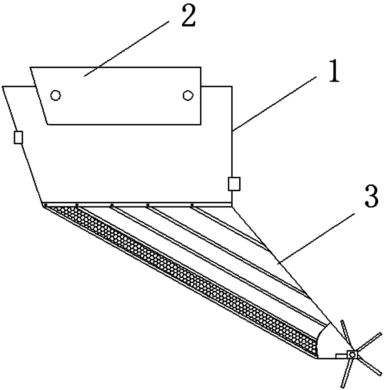
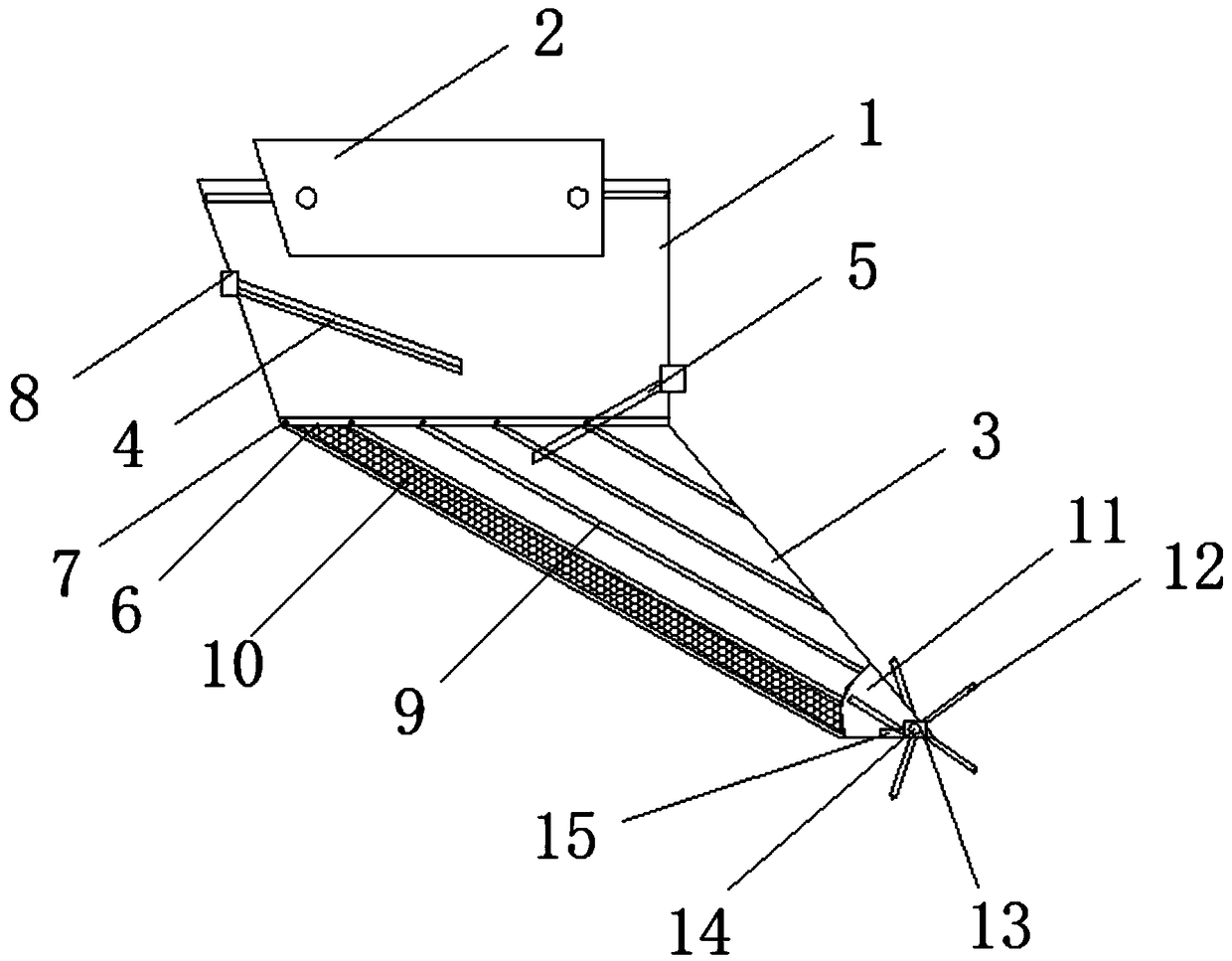
[0018] see Figure 1-2 As shown, a special-shaped bag cage for filter material includes a feed hopper 1 and a bag cage 9 at the bottom thereof. The top of the feed hopper 1 is provided with a feed inlet 2, and a filter bag 3 is sleeved on the outer wall of the bag cage 9. And the bottom of the bag cage 9 is provided with a discharge port 11, the first filter plate 4 is installed on the inner wall of one side of the feeding hopper 1, and the second filter plate 5 guiding the inside of the bag cage 9 is installed on the outer wall of the other side of the feeding hopper 1; The top of each skeleton constituting the bag cage 9 is connected to the bottom of the feed hopper 1, and a seal 6 is installed at the joint between the bag cage 9 and the feed hopper 1, and several screw holes 7 are arranged on the seal 6, and the bag A layer of screen 10 is sleeved on the inner wall of the inclined side of the cage 9, so that the filter material in the area where the material is accumulated ...

Embodiment 2

[0020] Please continue to refer to Figure 1-2 The difference between it and the above-mentioned embodiment is that one end of the first filter plate 4 and the second filter plate 5 are respectively inserted into two joints 8 located on the inner wall of the feed hopper 1 and fixed. The angle between the first filter plate 4 and the inner wall of the feed hopper 1 is 45°, and the angle between the second filter plate 5 and the inner wall of the feed hopper 1 is 60°, so that when the material enters from the feed hopper 1 It can be filtered by the filter holes on the two filter plates and flow to the inside of the filter bag 3 under the guidance of the second filter plate 5 . Each skeleton of the bag cage 9 is connected to a corresponding screw hole 7, and the bag cage 9 is fixedly connected with the feed hopper 1 and the filter bag 3 by a seal 6, so that the feed hopper 1 and the bag cage 9 and The filter bag 3 constitutes a stable whole, and a special-shaped bag cage is form...


PUM


Abstract

The invention discloses a special bag cage for filtering materials. The special bag cage comprises a feeding hopper, a feeding port, a filtering bag, a first filtering plate, a second filtering plate,a sealing strip, screw holes, joints, a bag cage, a sieving net, a discharging port, a swinging wheel, a motor, a rotary shaft and a power supply. The special bag cage disclosed by the invention hasthe beneficial effects that the special bag cage is formed between the feeding hopper and the filtering bag, so that the special bag cage can be applicable to the filtering materials with special conditions; since the feeding port is internally provided with the first filtering plate and the second filtering plate fixed by the two joints, materials can be filtered by filtering holes in the two filtering plates when entering from the feeding hopper and flow into the filtering bag; a sieving net with smaller hole diameter sheathes on the inner wall of the inclined side of the filtering bag, so that the material filtering effect of a material stacking area on the filtering bag is better; the discharging port with a sector-shaped structure is arranged at the bottom part of the filtering bag and is used for discharging waste materials left in the filtering bag, and the discharging port is internally provided with the swinging wheel, and the middle part of the swinging wheel is connected with the rotary shaft of the motor.

Description

technical field [0001] The invention relates to a bag cage, in particular to a special-shaped bag cage for filter materials, which belongs to the field of bag cages. Background technique [0002] The bag cage is an indispensable main accessory of the bag filter. It is used as the keel to support the dust bag. It can be divided into six, eight, ten, twelve, sixteen, eighteen, twenty, and twenty-four. Ribs are widely used in the dust removal industry and steel, chemical, coking, coal mines, non-ferrous smelting, etc. Now the bag cage is used for the filter material, and the waste in the material is screened out by using the bag cage. However, the existing filter material is used The filter effect of the bag cage is not good during use, and the discharge port of the bag cage is easy to block when the waste is discharged. Contents of the invention [0003] The purpose of the present invention is to provide a kind of filter material in order to solve the problem that the above...

Claims


Application Information

Patent Timeline
Patent Type & Authority Applications(China)
IPC IPC(8): B01D29/27B01D29/50
CPCB01D29/27B01D29/50
Inventor 蒋文树
Owner JIANGSU FUSHENG ENVIRONMENTAL PROTECTION GROUP
Features
  • R&D
  • Intellectual Property
  • Life Sciences
  • Materials
  • Tech Scout
  • Unparalleled Data Quality
  • Higher Quality Content
  • 60% Fewer Hallucinations
Learn More