

Overflow-type heat exchanger of urban sewage source heat pump system
A technology of urban sewage and heat exchange devices, applied in heat recovery systems, heat pumps, heat exchangers, etc., can solve the problems of large floor area and complicated process flow, and achieve small floor space, simplified process flow, and land occupation small effect
- Summary
- Abstract
- Description
- Claims
- Application Information
AI Technical Summary
Problems solved by technology
Method used
Image

Examples
specific Embodiment approach 1
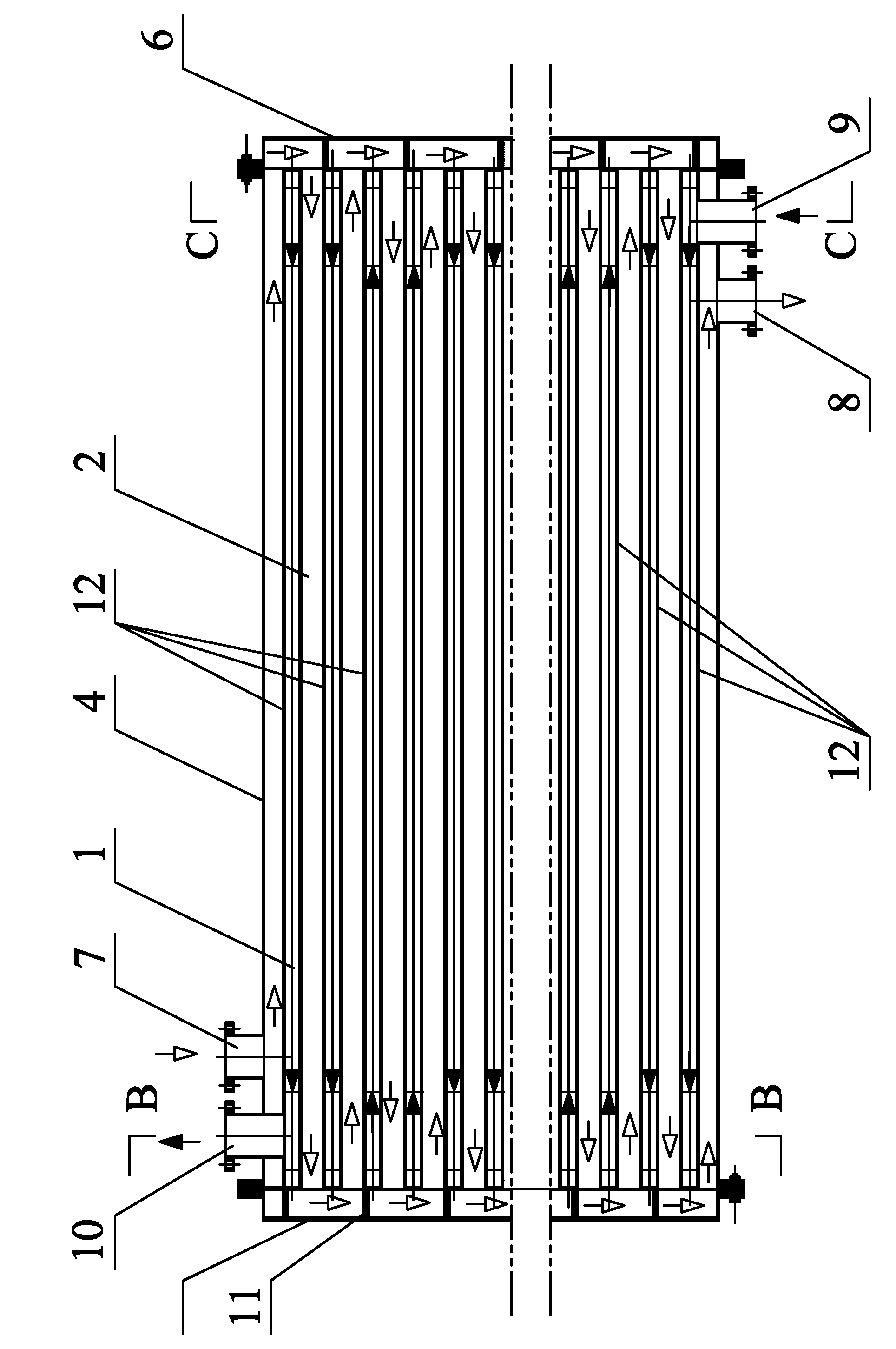
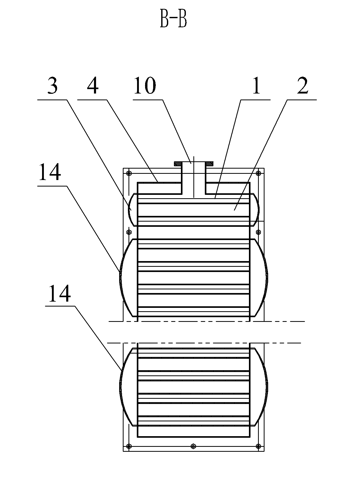
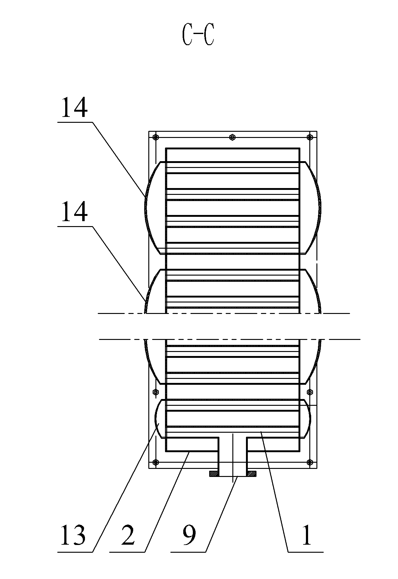
[0015] Specific implementation mode one: combine Figure 1-Figure 4 To illustrate this embodiment, the urban sewage source heat pump system flow heat exchange device in this embodiment includes an outer shell 4, a left head 5, a right head 6, a sewage inlet 7, a sewage outlet 8, a medium inlet 9, and a medium outlet 10 , a plurality of head partitions 11 and a plurality of square tube rows or plywood layers 12, the plurality of square tube rows or plywood layers 12 are fixedly installed in the outer shell 4 from top to bottom to form a tube shell assembly, the square tube Inside the row or plywood layer 12 is a medium flow channel 1, between two adjacent square tube rows or plywood layers 12, between the top square tube row or plywood layer 12 and the inner wall of the upper end plate of the outer shell 4, and between the bottom end Between the square pipe row or plywood layer 12 and the inner wall of the lower end plate of the outer shell 4 is a sewage flow channel 2, and the...
specific Embodiment approach 2
[0016] Specific implementation mode two: combination Figure 1-Figure 3 To describe this embodiment, the height of the sewage channel 2 in this embodiment is 30mm-60mm, and the height of the medium channel 1 is 10mm-20mm. With such arrangement, the height of the medium flow channel is reduced by 50%-75%, and the height or volume of the flow-through heat exchange device is reduced by 25%-37.5%. Other compositions and connections are the same as in the first embodiment.
specific Embodiment approach 3
[0017] Specific implementation mode three: combination figure 1 The present embodiment will be described. In this embodiment, the height of the sewage channel 2 is 40 mm, and the height of the medium channel 1 is 20 mm. With such arrangement, the height of the medium flow channel is reduced by 75%, and the height or volume of the flow-through heat exchange device is reduced by 37.5%. Other compositions and connections are the same as those in the second embodiment.
[0018] The operating principle is: sewage containing suspended solids and other impurities enters from the sewage inlet 7, flows through each sewage flow channel in series from the first sewage flow channel at the entrance, and flows out from the sewage outlet 8 of the sewage flow channel at the exit , see the route of sewage flow figure 1 The hollow arrow in ; the medium enters from the medium inlet 9, and the two or three or four parallel medium flow channels 1 from the inlet flow through the medium flow chann...
PUM
| Property | Measurement | Unit |
|---|---|---|
| Height | aaaaa | aaaaa |
| Height | aaaaa | aaaaa |
Abstract
Description
Claims
Application Information