Supercharge Your Innovation With Domain-Expert AI Agents!

Multi-speed-ratio independent transmission rolling mill and rolling method

A technology with independent transmission and multiple speed ratios, which is applied in metal rolling, metal rolling, and driving devices for metal rolling mills. impact and other issues, to achieve the effect of simplifying the equipment structure, improving flexibility, and simple and compact structure

Pending Publication Date: 2019-01-18
CISDI RES & DEV CO LTD
View PDF8 Cites 2 Cited by
  • Summary
  • Abstract
  • Description
  • Claims
  • Application Information

AI Technical Summary

Problems solved by technology

However, for high-speed wire rods, the typical product diameter range is Φ5.0mm~Φ25.0mm, the production speed range is Φ8.0m / s~115m / s, and the rolling force is limited by the rolling force when single-speed ratio rolling is used. Influenced by the torque, the process adjustment can only be carried out on a specific rolling stand, which is difficult to adjust, and is affected by the process layout, so the temperature of the rolled piece cannot be flexibly controlled, which is not conducive to the control of the rolling temperature of the wire rod

Method used


Image

  • Multi-speed-ratio independent transmission rolling mill and rolling method
  • Multi-speed-ratio independent transmission rolling mill and rolling method
  • Multi-speed-ratio independent transmission rolling mill and rolling method

Examples


Embodiment 1

[0031] Such as Figure 1-4 As shown, this embodiment provides an independent drive rolling mill with double speed ratios, including a gearbox 4 with two speed ratios, a rolling mill 1 , and a motor 6 . The input shaft 4-1 of the gearbox 4 is provided with an idler gear 4a, and realizes synchronous rotation or free rotation with the input shaft 4-1 through the clutch 4-3. The output shaft 4-2 is provided with a fixed gear 4b which is fixedly connected with the output shaft, and is respectively meshed with the idler gear 4a on the input shaft 4-1, and the switching of different speed ratios is realized through the clutch 4-3. Under certain conditions, the rotational speed and torque of the output shaft 4-2 are changed to meet the speed ratio requirements of different rolling processes.

[0032] The input shaft 4-1 and the output shaft 4-2 of the gearbox 4 in this embodiment are vertically arranged to reduce the width of the gearbox so as to realize a compact arrangement.

[00...

Embodiment 2

[0035] Such as Figure 5 As shown, this embodiment is an independent transmission rolling mill with double transmission ratios like Embodiment 1, but the difference is that the clutch 4-3 of the gearbox 4 can also be arranged on the output shaft 4-2, that is, the input shaft 4 The fixed gear 4b provided on -1 is fixedly connected with the input shaft, and the idler gear 4a provided on the output shaft 4-2 is connected with the output shaft idler, which can also realize switching of different speed ratios.

Embodiment 3

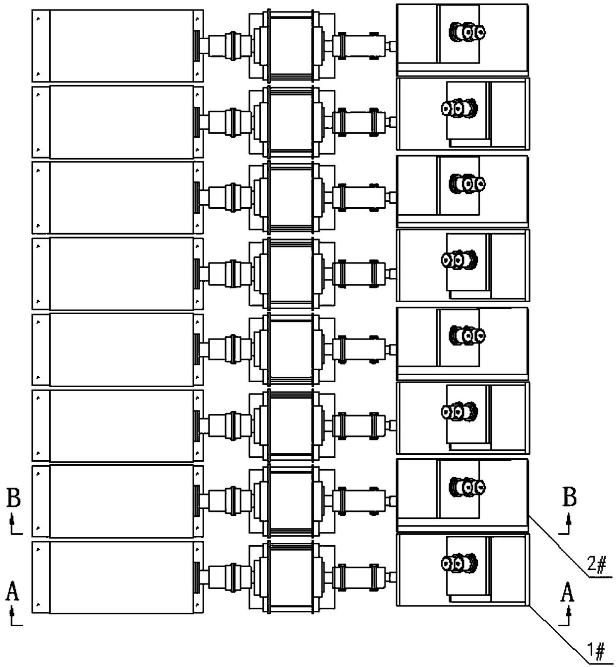
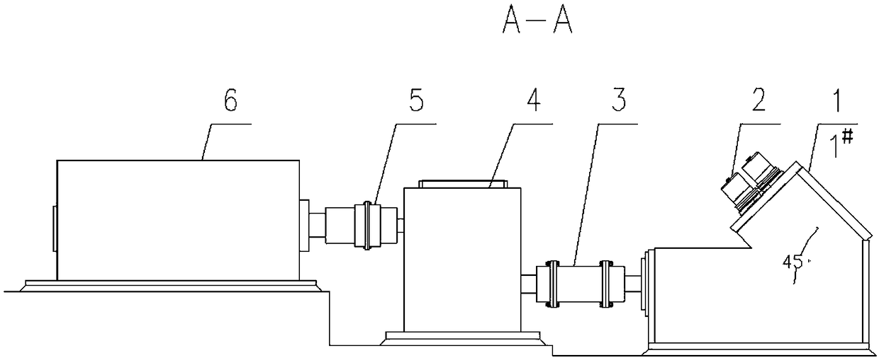
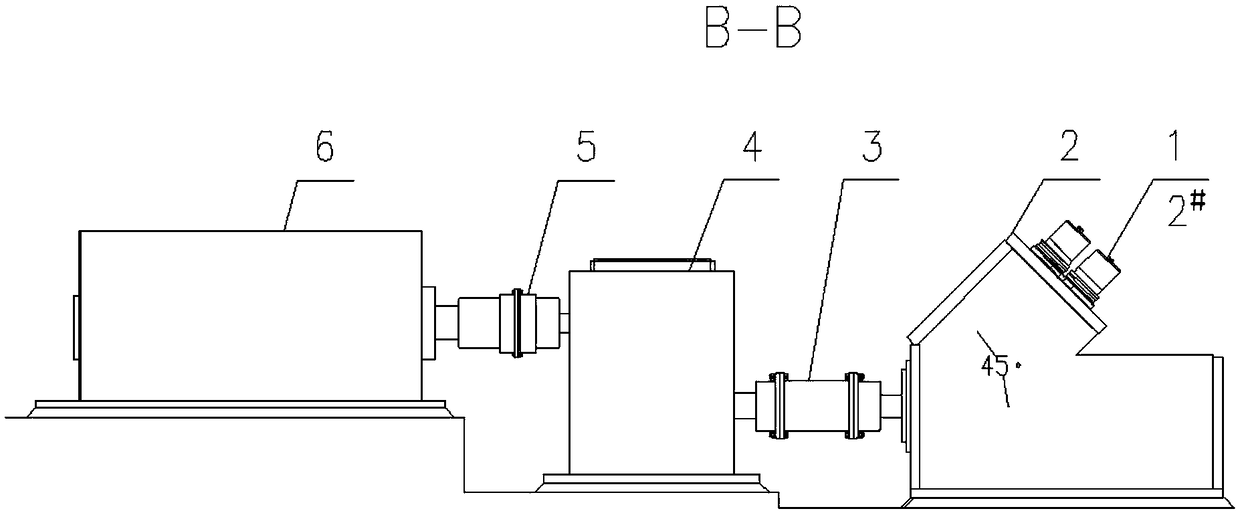
[0037] Such as Image 6 As shown, the present embodiment is different from the above-mentioned embodiments in that it has an independent transmission rolling mill with multiple speed ratios, that is, the gearbox 4 can realize more speeds by increasing the number of intermediate shafts 4-4 and clutches 4-3. Ratio output, thus forming independent rolling mill row 1# and rolling mill row 2# with more speed ratios, increasing the output of speed ratios and the combination of speed ratios, further improving the flexibility of production.


PUM


Abstract

The invention discloses a multi-speed-ratio independent transmission rolling mill and belongs to the field of metallurgical equipment. The rolling mill comprises rolling mill bodies, gearboxes and motors. Each gearbox has at least two speed ratios and is internally provided with an input shaft connected with the corresponding motor, an output shaft connected with the corresponding rolling mill body and a clutch used for achieving switching of different speed ratios of the gearboxes. The multi-speed-ratio independent transmission rolling mill meets the requirements for high-speed rolling of wire rods, the equipment structure is optimized, the production flexibility is improved, and convenience is provided for achieving high-speed temperature-controlled rolling of the wire rods.

Description

technical field [0001] The invention belongs to the technical field of metallurgical rolling equipment, and in particular relates to a multi-speed ratio independent transmission rolling mill and a rolling method. Background technique [0002] In modern wire rod production, the method of increasing the final rolling speed of wire rod is usually adopted to obtain higher output. Traditional high-speed wire rod mills have been using centralized transmission for many years, that is, a large motor drives 8 to 10 wire rod finishing mills at the same time to achieve 45° twist-free rolling at the top. The two long shafts respectively drive multiple groups of rolling mill gear sets, and through mechanical interlocking, the problem of dynamic speed drop of the rolling mill is solved and stable production is achieved. Although centralized transmission can be used to achieve mechanical interlocking, there are always many problems such as complex equipment structure, difficult vibration ...

Claims


Application Information

Patent Timeline
Patent Type & Authority Applications(China)
IPC IPC(8): B21B35/12B21B35/14
CPCB21B35/12B21B35/14
Inventor 陈莹卷周民牛强李图学马靳江
Owner CISDI RES & DEV CO LTD
Features
  • R&D
  • Intellectual Property
  • Life Sciences
  • Materials
  • Tech Scout
  • Unparalleled Data Quality
  • Higher Quality Content
  • 60% Fewer Hallucinations
Learn More