Rapid die clamping system for bending machine

A bending die and bending machine technology, applied in the field of bending machines, can solve the problems of low die changing efficiency, high labor intensity, complicated operation, etc., achieve consistent clamping force, reduce labor intensity of workers, and improve operation efficiency. Effect

Pending Publication Date: 2019-01-18
王勇
View PDF0 Cites 1 Cited by
  • Summary
  • Abstract
  • Description
  • Claims
  • Application Information

AI Technical Summary

Problems solved by technology

Generally, a bending machine with a 3-meter-long workbench needs to be equipped with 15-20 manual quick clamps. For example, if a bending machine with a 3-meter-long workbench is filled with molds, the operator needs to Repeat the loosening and locking actions 15-20 times each. Even simply moving the position of the lower mold left and right is time-consuming and laborious. Low efficiency and other disadvantages

Method used


Image

  • Rapid die clamping system for bending machine
  • Rapid die clamping system for bending machine
  • Rapid die clamping system for bending machine

Examples


Embodiment 1

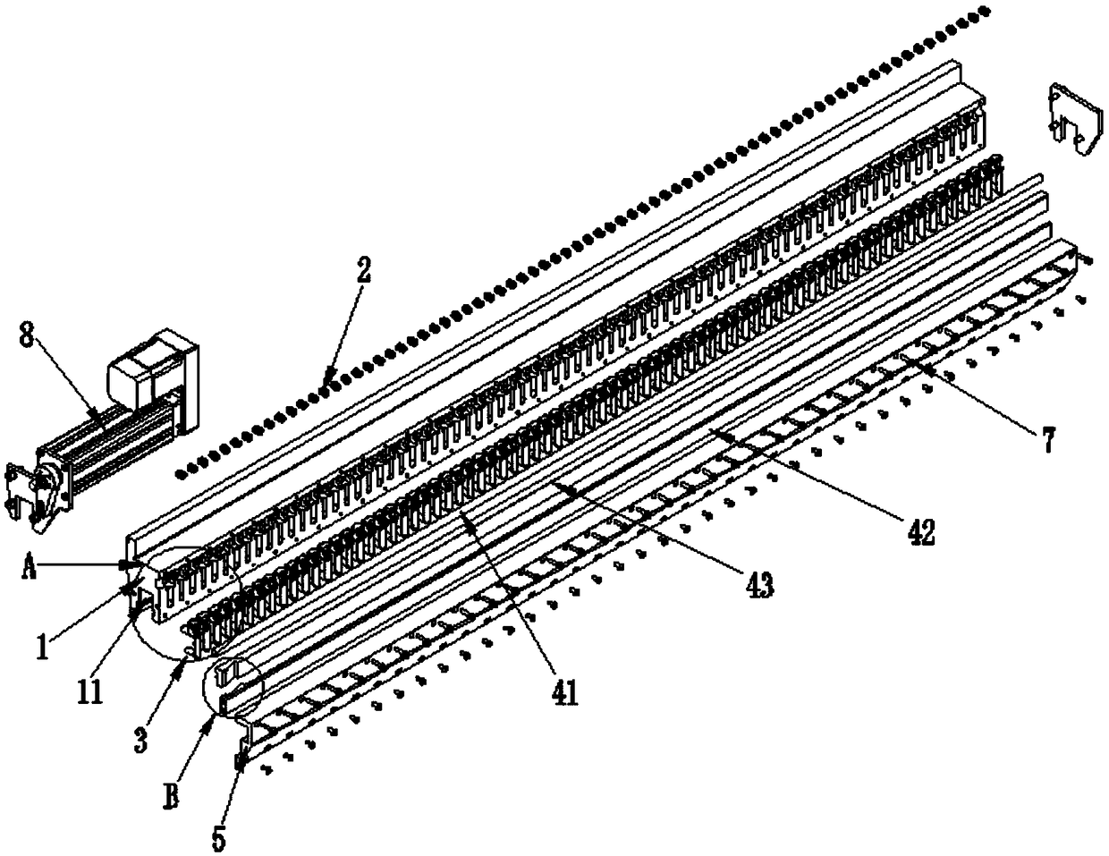
[0038] Such as Figure 1 to Figure 5 As shown, a quick mold clamping system for a bending machine includes a clamping base 1, clamping teeth 3, a pushing mechanism 4, and a reset elastic member.

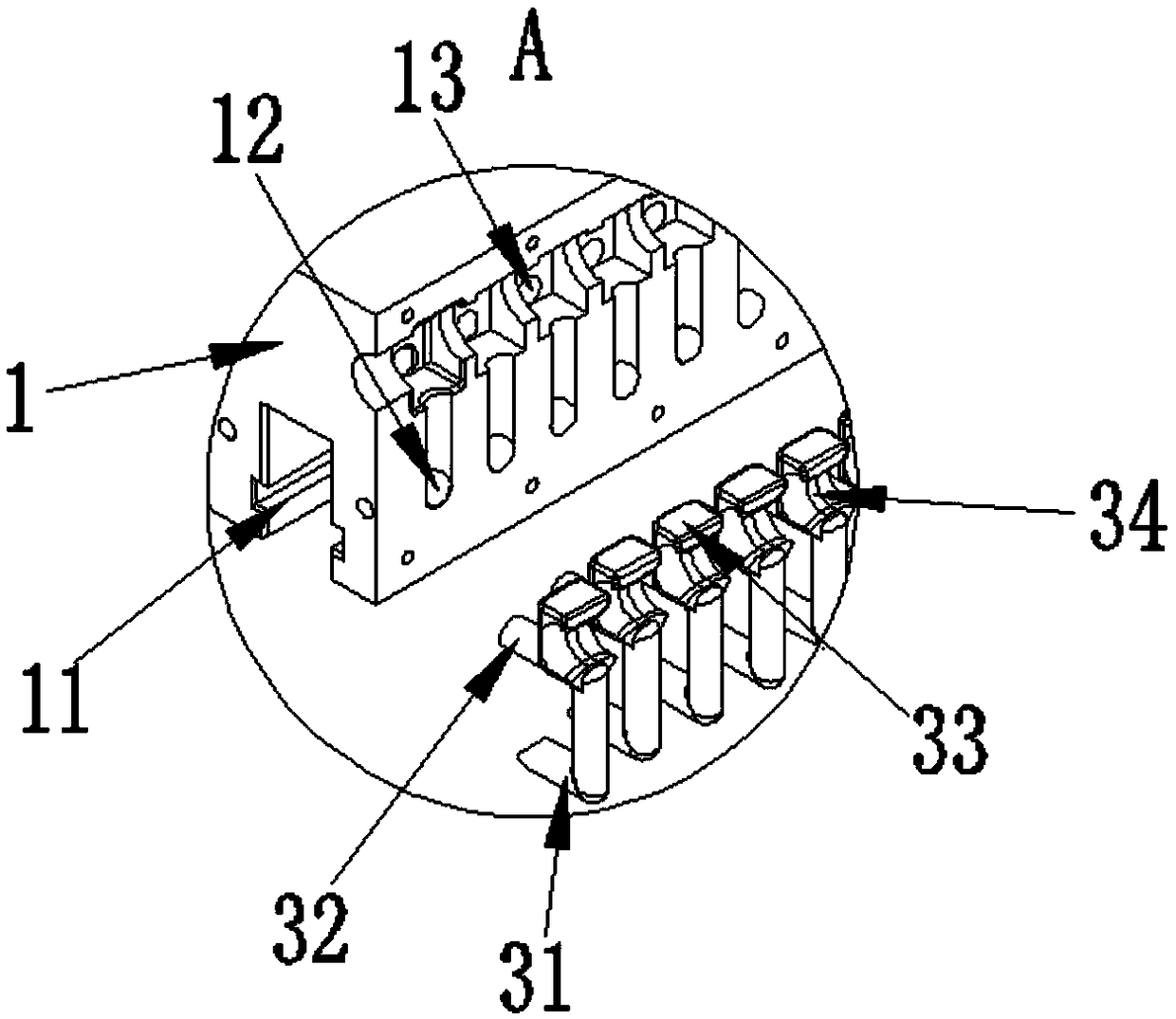
[0039] The clamping base 1 is provided with a first installation groove 11 for installing the bending die 6 and a sliding groove 12 for passing through the clamping end 31 of the clamping tooth 3, and the sliding groove 12 extends to the first The installation groove 11 communicates with the first installation groove 11 . The upper end of the bending die 6 is installed in the first installation groove 11, one side of the bending die 6 is close to the wall groove of the first installation groove 11, and the other side of the bending die 6 is used to connect with the clamping teeth 3 The snap-in end 31 cooperates, and the bending die 6 is clamped by the snap-in end 31 pressing the bending die 6 . The entire clamping base 1 is subjected to corresponding heat treatment process for stre...

Embodiment 2

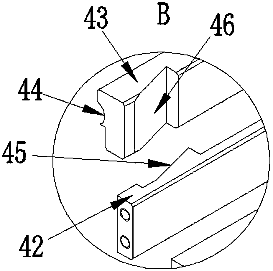
[0055] As a preferred solution, the difference between Embodiment 2 and Embodiment 1 is that the movable wedge 42 is provided with a plurality of first slopes 45 on the side contacting with the rubber hose wedge 43. Similarly, the rubber hose wedge The number of the second slope 46 on the movable wedge 43 is the same as that of the first slope 45 on the movable wedge 42 and corresponds to each other.

[0056] Such as Figure 6 to Figure 8 As shown, a plurality of first slopes 45 are evenly arranged on the movable wedge 42, and two adjacent first slopes 45 are connected by a third slope 47, and the first slope 45 and the third slope 47 form a zigzag structure ; The second slope 46 on the hose wedge 43 is also uniformly provided with a plurality, each second slope 46 cooperates with the corresponding first slope 45, and the fourth slope 48 passes between two adjacent second slopes 46 connection, wherein, the fourth slope 48 cooperates with the third slope 47; when the movable w...

Embodiment 3

[0061] The difference between Embodiment 3 and Embodiment 1 lies in the structure of the pushing mechanism 4 and the structure of the head end 33 of the clamping tooth 3 .

[0062] Such as Figure 9 to Figure 12 As shown, the clamping tooth 3 also includes a head end 33, and the pushing mechanism 4 includes a first pulley 49 installed on the clamping base 1, a second pulley 49 installed on the head end 33 of each clamping tooth Pulley 410, and the steel belt 411 that is wound on the first pulley 49 and the second pulley 410 so that the first pulley 49 and the second pulley 410 form a movable and fixed pulley block structure, and one end of the steel belt 411 is fixed on the clamp On the base 1 , a steel belt fixing block 14 is provided on one side of the clamping base 1 , and one end of the steel belt 411 is fixed on the steel belt fixing block 14 . The other end of the steel belt 411 is connected to the second electric servo drive device 9 , and the steel belt 411 is pulled ...


PUM


Abstract

The invention discloses a rapid die clamping system for a bending machine. The system comprises a clamping base, clamping teeth, a pushing mechanism and a reset elastic part. A first mounting groove for mounting of a bending die and a sliding groove for penetrating through the clamping ends of clamping teeth are formed in the clamping base. The sliding groove is communicated with the first mounting groove. The clamping teeth are mounted on the clamping base, and comprise the clamping ends, and the clamping ends are slidingly assembled in the sliding groove. The pushing mechanism is used for wholly pushing the clamping teeth to enable the clamping ends to slide to the first mounting groove along the sliding groove. The reset elastic part is mounted between the clamping teeth and the clamping base and used for wholly pushing the clamping teeth to enable the clamping ends to slide opposite to the first mounting groove along the sliding groove. The bending die can be rapidly clamped and loosened, one-key clamping is achieved, it is avoided that dozens of times of operations need to be repeated in traditional manual rapid clamping, the die replacement time is saved, and the operation efficiency is improved.

Description

technical field [0001] The invention relates to a quick mold clamping system for a bending machine, which belongs to the technical field of bending machines. Background technique [0002] The manual quick clamp is installed on the upper slider of the bending machine. The up and down movement of the upper slider drives the mold to move up and down, and the mold is pressed on the workpiece to bend the workpiece into a specific shape. At present, most of the existing quick clamps of bending machine molds are manual quick clamps, and the molds are clamped by manual quick clamps. Generally, a bending machine with a 3-meter-long workbench needs to be equipped with 15-20 manual quick clamps. For example, if a bending machine with a 3-meter-long workbench is filled with molds, the operator needs to Repeat the loosening and locking actions 15-20 times each. Even simply moving the position of the lower mold left and right is time-consuming and laborious. Low efficiency and other sho...

Claims


Application Information

Patent Timeline
Patent Type & Authority Applications(China)
IPC IPC(8): B21D37/14
CPCB21D37/14
Inventor 王勇林艳
Owner 王勇
Why Eureka
Try Eureka