Honeycomb core welding machine frame

A technology of welding frame and honeycomb core, applied in welding equipment, welding equipment, auxiliary welding equipment and other directions, can solve the problem of low production efficiency of honeycomb core welding frame, improve adaptability and versatility, improve welding efficiency, The effect of saving production costs

Active Publication Date: 2019-01-18
MAANSHAN ANDER TECH
View PDF6 Cites 0 Cited by
  • Summary
  • Abstract
  • Description
  • Claims
  • Application Information

AI Technical Summary

Problems solved by technology

[0005] The main purpose of the present invention is to provide a honeycomb core welding frame to solve the problem of low production efficiency of the honeycomb core welding frame in the prior art

Method used


Image

  • Honeycomb core welding machine frame
  • Honeycomb core welding machine frame
  • Honeycomb core welding machine frame

Examples


Embodiment 1

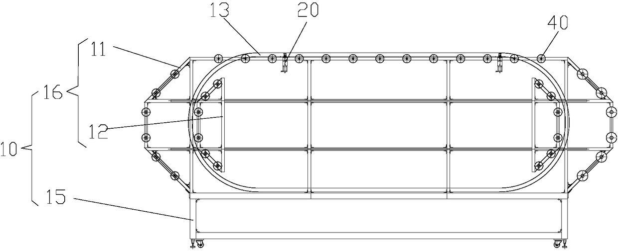
[0035] like figure 1 A honeycomb core welding frame shown includes a frame 10 and a clamping mechanism 20, the frame 10 has a fixed part 11 and a movable part 12, the fixed part 11 and the movable part 12 are movably connected, and the frame 10 has an annular ring supporting the honeycomb core The support area 13, and at least a part of the annular support area 13 is formed by the movable part 12, so that the size of the annular support area 13 changes with the movement of the movable part 12; the clamping mechanism 20 is movably connected with the frame 10 and the honeycomb core, and drives The honeycomb core moves along the annular support zone 13 .

[0036] In this embodiment, the honeycomb core is supported by the annular support area 13 of the frame 10, and the size of the annular support area 13 can be changed following the movement of the movable part 12, so that the annular support area 13 can be adapted to the size of the honeycomb core, improving It improves the ada...

Embodiment 2

[0054] The difference from the first embodiment is that the fixed part 11 is slidably connected to the movable part 12, and the movable part 12 slides along the vertical direction.

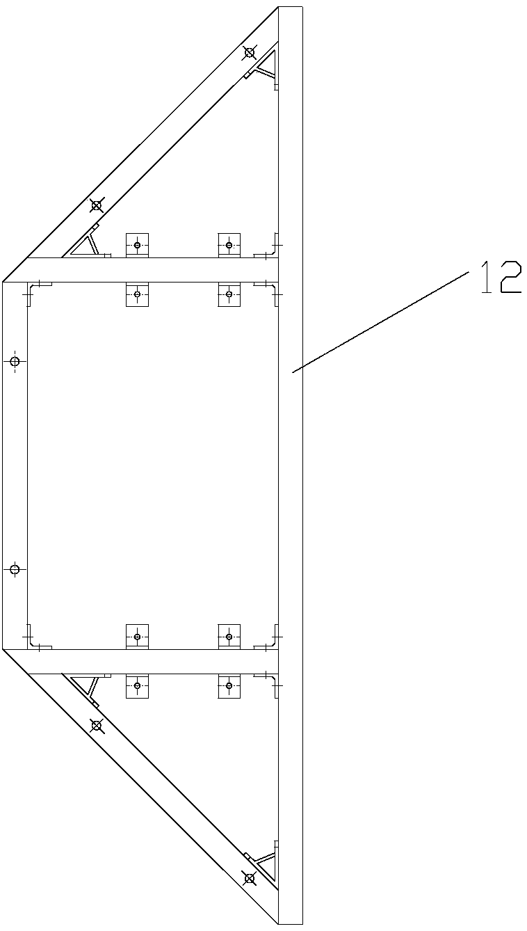
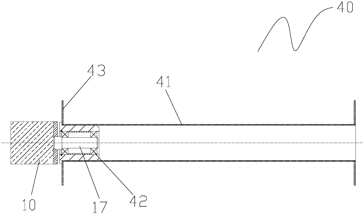
[0055] like Figure 4 As shown, the fixed part 11 is a column, and the movable part 12 forms an annular support area 13. Specifically, the movable part 12 has a plate-shaped piece arranged horizontally, and a plurality of extending arms 14 are arranged on the plate-shaped piece. The end of 14 and the plate-like member are provided with idler mechanisms 40, and at least some of the idler mechanisms 40 have different heights, the honeycomb core is supported on the idler mechanisms 40, and at least part of the extended arms 14 form an annular support area 13, The clamping mechanism 20 is connected with the plate to lock and unlock the honeycomb core and the plate, and can also drive the honeycomb core to move.

[0056] In this embodiment, the honeycomb core welding frame further includes a lifting m...


PUM


Abstract

The invention provides a honeycomb core welding machine frame. The honeycomb core welding machine frame comprises a frame body and a clamping mechanism, wherein the frame body is provided with a fixedpart and a movable part, the fixed part is movably connected with the movable part, the frame body is provided with an annular supporting area used for supporting a honeycomb core, and at least one part of the annular supporting area is formed by the movable part, so that the size of the annual supporting area is changed along with movement of the movable part; the clamping mechanism is movably connected with the frame body and the honeycomb core and drives the honeycomb core to move along the annular supporting area. By means of the honeycomb core welding machine frame, the problem is solvedthat in the prior art, the production efficiency of a honeycomb core welding machine frame is low.

Description

technical field [0001] The invention relates to the technical field of honeycomb core welding, in particular to a honeycomb core welding frame. Background technique [0002] The honeycomb core is a new type of material. The lattice adopts a regular hexagonal structure. The hexagonal structure is stable and saves materials. It is a new type of material. The metal honeycomb core has good mechanical properties, good durability, and thermal conductivity. As a new material, it is widely used in aviation, electronics, machinery and other fields. [0003] The honeycomb core is manufactured by welding. After the sheet material is formed, it is welded grid by grid, and finally becomes a product for application manufacturing. The existing manufacturing method of the honeycomb core is mainly stacked production, and a single piece is tailor-welded, and the tailor-weld speed is slow, and it is impossible to realize automated mass production. [0004] Existing honeycomb tailor welding e...

Claims


Application Information

Patent Timeline
Patent Type & Authority Applications(China)
IPC IPC(8): B23K31/00B23K37/00B23K37/04
CPCB23K31/00B23K37/00B23K37/0443
Inventor 郑立刚张大琦潘志金尹名庆郑立桐
Owner MAANSHAN ANDER TECH
Why Eureka
Try Eureka