
Secondary positioning table suitable for bearing workpiece machining and positioning method

A positioning table and bearing technology, which is applied in the field of bearing workpiece processing, can solve the problems of not being stuck, changing the face, affecting the precision and accuracy of processing operations, etc., achieving strong practicability, ensuring precise contact, and improving safety protection sexual effect

Pending Publication Date: 2019-01-18
BEIFANG UNIV OF NATITIES
View PDF0 Cites 3 Cited by
  • Summary
  • Abstract
  • Description
  • Claims
  • Application Information

AI Technical Summary

Problems solved by technology

[0003] The traditional processing and positioning technology of bearing workpieces uses V-shaped grooves to position the bearing workpieces in line contact, that is, two V-shaped positioning grooves with angles clamp the joint bearing in the middle, when the bearing workpieces are in contact with the V-shaped grooves When the width of the surface is relatively narrow, the position of the bearing workpiece will change during the positioning process, resulting in the problem of card deviation or even failure to change the surface, which affects the precision and accuracy of the processing operation.

Method used


Image

  • Secondary positioning table suitable for bearing workpiece machining and positioning method
  • Secondary positioning table suitable for bearing workpiece machining and positioning method
  • Secondary positioning table suitable for bearing workpiece machining and positioning method

Examples


Embodiment 1

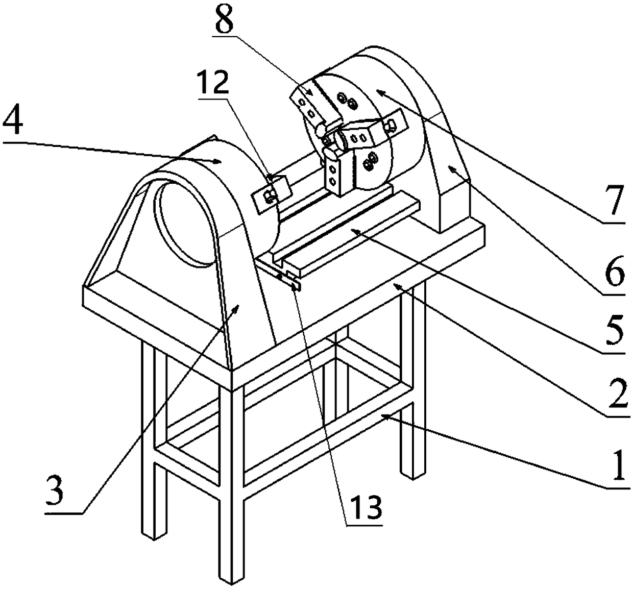
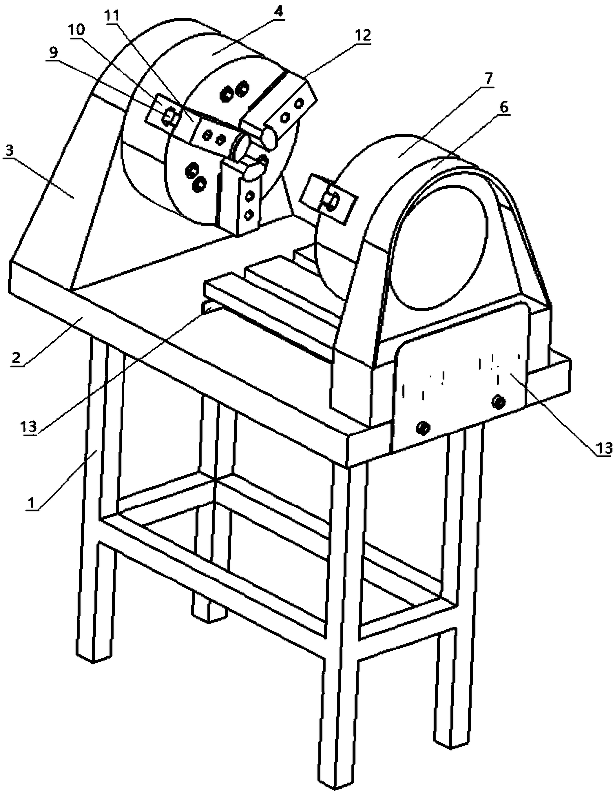
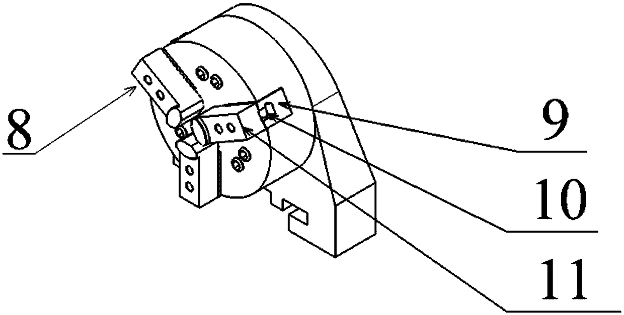
[0031] A secondary positioning table suitable for machining bearing workpieces, such as figure 1 , figure 2 with image 3 As shown, it includes a base support frame 1, a base support platform 2, a fixed chuck support 3, a fixed chuck base 4, a mobile transmission device 5, a mobile chuck support 6, a mobile chuck base 7, and a mobile chuck inner finger 8 , the chuck slider 9, the chuck finger pad 10, the chuck finger 11, the fixed chuck inner finger 12 and the baffle plate 13; the base support frame 1 is provided with a base support platform 2; The two ends of the upper surface of the base support platform 2 are relatively parallel with a fixed chuck support 3 and a movable chuck support 6;

[0032] The inner side of the upper part of the fixed chuck support 3 is provided with a cylindrical fixed chuck base 4, and the fixed chuck base 4 is provided with at least three fixed chuck internal grasping fingers 12, and the fixed chuck internal grasping fingers 12 include The chu...

Embodiment 2

[0037] A positioning method suitable for machining bearing workpieces, comprising the following steps:

[0038] a. The bearing workpiece is clamped and fixed by the finger 12 in the fixed chuck, and one end of the bearing workpiece is pushed against and fixed on the base 4 of the fixed chuck, and the processing operation of one end of the bearing workpiece is performed;

[0039] b. After the processing of one end of the bearing workpiece is completed, move the movable chuck base 7 along the mobile transmission device 5 to the fixed chuck base 4, so that the processed end of the bearing workpiece is pushed against the movable chuck base 7. The gripping finger 8 in the disk clamps and fixes the bearing workpiece;

[0040] c. Open the inner gripping finger 12 of the fixed chuck, move the movable chuck base 7 along the moving transmission device 5 away from the fixed chuck base 4 and return to the original position, complete the surface change, and then process the unprocessed end...


PUM


Abstract

The invention relate to the field of bearing workpiece machining, in particular to a secondary positioning table suitable for bearing workpiece machining and a positioning method. The secondary positioning table comprises a base supporting table, a positioning device fixed to the base supporting table, and a movable conveying device matched with the positioning device. The positioning device comprises a fixed chuck support, a fixed chuck base, a fixed chuck inner grabbing finger, a movable chuck support, a movable chuck base and a movable chuck inner grabbing finger. The fixed chuck support and the movable chuck support are arranged at the two ends of the upper surface of the base supporting table in parallel. The fixed chuck base is arranged on the inner side of the upper portion of the fixed chuck support. The fixed chuck inner grabbing finger is arranged on the fixed chuck base. The movable chuck base is arranged on the inner side of the upper portion of the movable chuck support. The movable chuck inner grabbing finger is arranged on the movable chuck base. The fixed chuck base and the movable chuck base are coaxially arranged. The movable conveying device is fixedly arranged at the position, on one side of the movable chuck support, of the base supporting table. The movable chuck support is axially slidingly connected to the movable conveying device.

Description

technical field [0001] The invention relates to the field of bearing workpiece processing, in particular to a secondary positioning table and a positioning method suitable for bearing workpiece processing. Background technique [0002] Bearing is an important part of contemporary mechanical equipment. Its main function is to support the mechanical rotating body, reduce the friction coefficient during its movement, and ensure its rotation accuracy. With the rapid development of my country's bearing industry, the variety of bearings has changed from few to many, the product quality and technical level have ranged from low to high, and the industry scale has grown from small to large. A professional production system with basically complete product categories and a relatively reasonable production layout has been formed. [0003] The traditional processing and positioning technology of bearing workpieces uses V-shaped grooves to position the bearing workpieces in line contact, ...

Claims


Application Information

Patent Timeline
IPC IPC(8): B25B11/00
CPCB25B11/00
Inventor 马行陈建宇穆春阳潘云龙安海平田国禾张春涛李茂强
Owner BEIFANG UNIV OF NATITIES
Learn More