Paper cutter with paper scrap removing mechanism for paper production

A paper cutter and utensil technology, applied in metal processing and other directions, can solve the problems of not enough environmental protection and economy, increase the cost of machinery manufacturing, not enough practicality, etc., and achieve the effects of easy cleaning operation, reduction of manufacturing cost, and simple structure

Inactive Publication Date: 2019-01-18
广州亿骏科技有限公司
View PDF11 Cites 0 Cited by
  • Summary
  • Abstract
  • Description
  • Claims
  • Application Information

AI Technical Summary

Problems solved by technology

[0004] The purpose of the present invention is to provide a paper cutter with a paper dust cleaning structure for paper production, so as to solve the problem that the existing paper proposed in the above background technology is not smooth enough due to the many edges and corners of the paper. edge trimming, and the general manufacturers use paper cutters to trim the paper edges, and the corners will be very messy when they are cut off, and the general paper cutters are not enough when dealing with paper scraps. Reasonable question, some machines will add special machinery such as fans and other mechanisms to deal with paper scraps, which increases the cost of production, and also increases the manufacturing cost of machinery, which is not environmentally friendly and economical, and has the problem of not being practical enough

Method used


Image

  • Paper cutter with paper scrap removing mechanism for paper production
  • Paper cutter with paper scrap removing mechanism for paper production
  • Paper cutter with paper scrap removing mechanism for paper production

Examples


Embodiment Construction

[0026] The following will clearly and completely describe the technical solutions in the embodiments of the present invention with reference to the accompanying drawings in the embodiments of the present invention. Obviously, the described embodiments are only some, not all, embodiments of the present invention. Based on the embodiments of the present invention, all other embodiments obtained by persons of ordinary skill in the art without making creative efforts belong to the protection scope of the present invention.

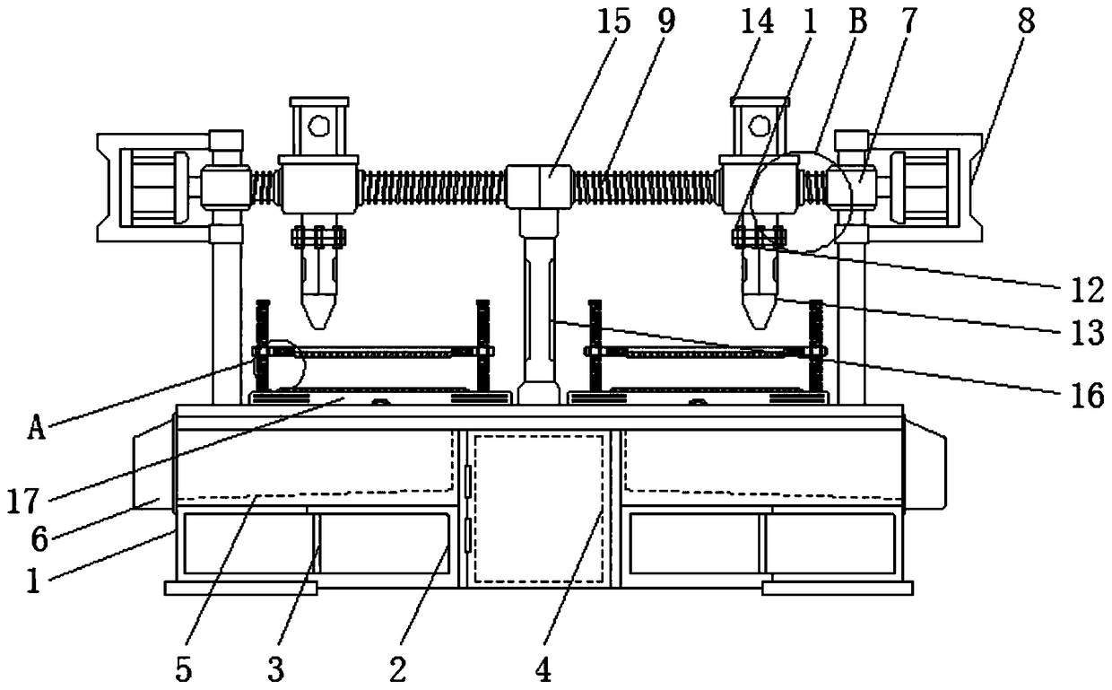
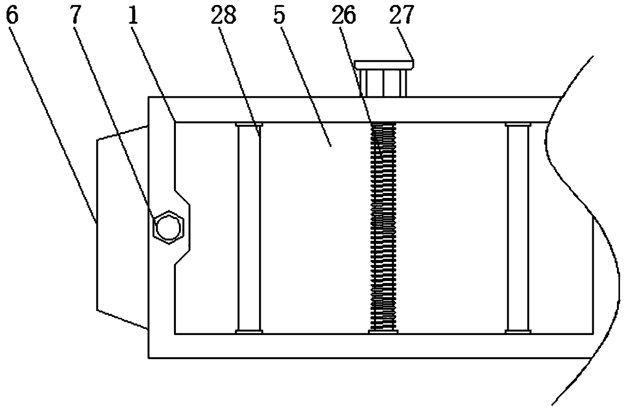
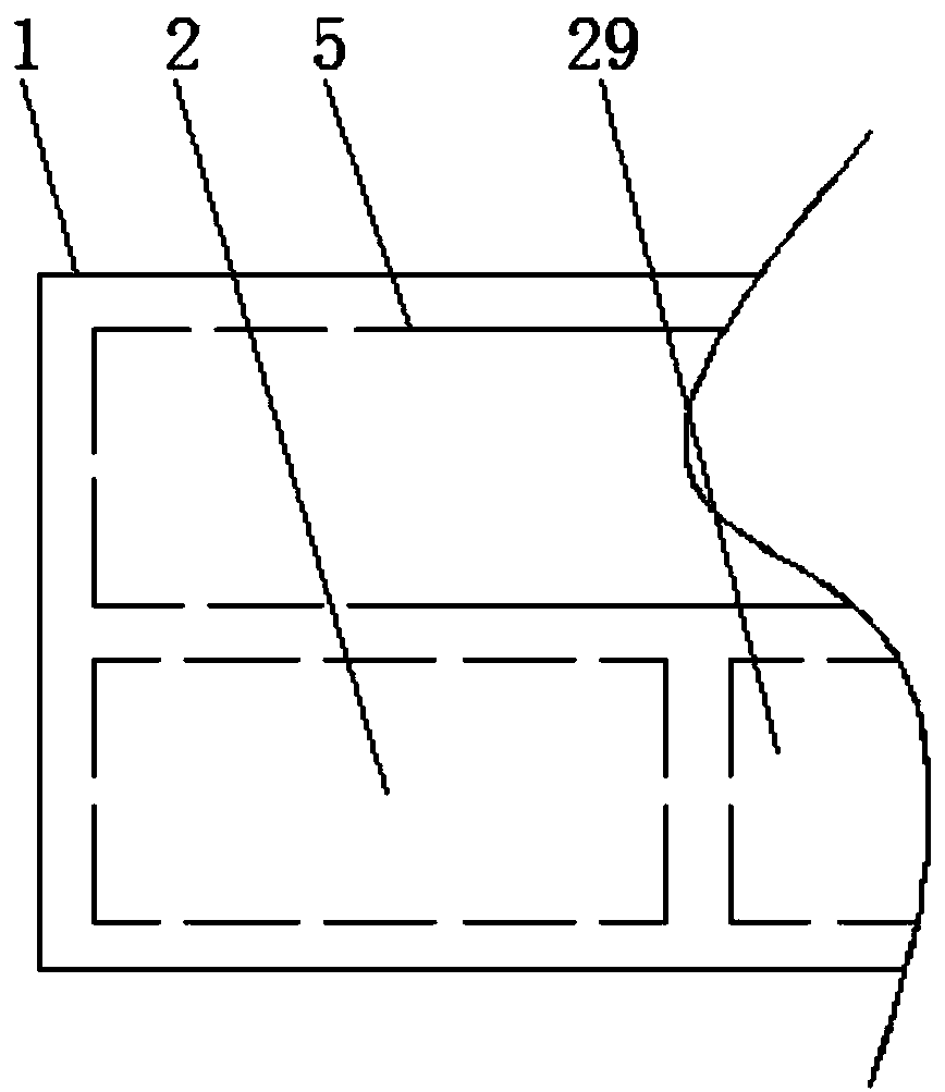
[0027] see Figure 1-5, the present invention provides a technical solution: a paper cutter with a paper dust cleaning structure for paper production, including a body 1, a storage room 2, a partition 3, a middle room 4, a discharge room 5, a discharge port 6, Connection side column 7, motor 8, suspension screw 9, transmission base 10, fixing bolt 11, connection suspension seat 12, cutter 13, hydraulic cylinder 14, center seat 15, support column 16, paper plac...


PUM


Abstract

The invention relates to a paper cutter with a paper scrap removing mechanism for paper production. The paper cutter comprises a cutter body and a discharge chamber. Placement chambers are arranged atthe left and right sides of the bottom end of the cutter body. A partition plate is linked to the inner end of each placement chamber. A middle chamber is placed in the middle of the bottom end of the cutter body. A discharging outlet is formed in the outer side of the discharge chamber. The discharge chamber is located at the upper ends of the placement chambers. The portions, above the middlesof the left and right ends, of the cutter body are each linked with a linkage edge column. The paper cutter with the paper scrap removing mechanism for paper production has the advantages that the linkage edge columns are arranged, a motor can be linked and placed through the linkage edge columns, fixation is performed conveniently, a suspension lead screw can be driven by motion of the motor to rotate, at the moment, a transmission machine base is driven by spiral force generated between a thread at the inner end of the transmission machine base and the suspension lead screw to displace, theworking position of the transmission machine base is conveniently adjusted, and a cutter can be better utilized for performing the cutting operation.

Description

technical field [0001] The invention relates to the technical field of paper cutters, in particular to a paper cutter with a paper dust cleaning structure for paper production. Background technique [0002] The paper cutter is a traditional product, which is used to deal with the paper cutting needs in the post-printing period. It has developed from a mechanical paper cutter to a tape-controlled paper cutter, and then to a computer program control, color display, full-image operation-guided visual processing and Computer-aided cutting The cutting system of external programming and editing production data makes the production preparation time shorter, the cutting precision is higher, the labor intensity is lower, and the operation is safer. [0003] When the existing paper is produced and processed, because the corners of the paper are not smooth enough, it is often necessary to trim the edges. However, ordinary manufacturers often use paper cutters to trim the edges of the p...

Claims


Application Information

Patent Timeline
Patent Type & Authority Applications(China)
IPC IPC(8): B26D1/09B26D7/26B26D7/01B26D5/02B26D7/18
CPCB26D1/095B26D5/02B26D7/015B26D7/18B26D7/2614
Inventor 廖钧邦
Owner 广州亿骏科技有限公司
Why Eureka
Try Eureka