Charging pile with rain shielding function

A charging pile and functional technology, applied in charging stations, electric vehicle charging technology, electric vehicles, etc., can solve the problems of charging guns without a fixed position, troublesome operation of replacing batteries, and easy entanglement of cables, etc., to achieve replacement or Easy maintenance and operation, simple structure, good practical effect

Inactive Publication Date: 2019-01-18
ZHEJIANG KANDI SMART BATTERY SWAP TECH CO LTD
View PDF6 Cites 1 Cited by
  • Summary
  • Abstract
  • Description
  • Claims
  • Application Information

AI Technical Summary

Problems solved by technology

[0003] At present, there are still shortcomings in the structure of charging piles for electric vehicles: the existing electric vehicle charging piles have unreasonable structural design and single functions. The battery is generally installed in the charging pile. Due to the small space in the charging pile, the heat dissipation performance of the battery is poor, and it is easy to generate heat. The service life is shortened, and it is troublesome to replace the battery; the charging gun has no fixed position, and it is very messy to place it randomly, and the cables used to connect the charging gun are easily entangled, which is inconvenient to use and poor in practicability

Method used


Image

  • Charging pile with rain shielding function
  • Charging pile with rain shielding function
  • Charging pile with rain shielding function

Examples


Embodiment Construction

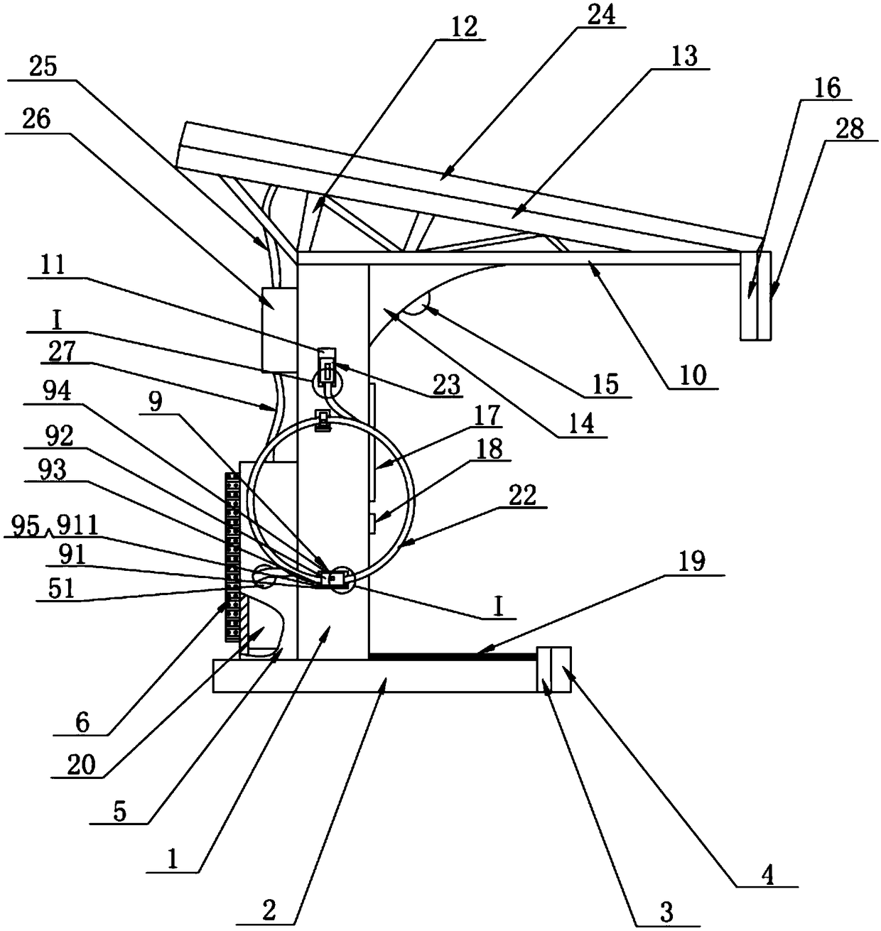
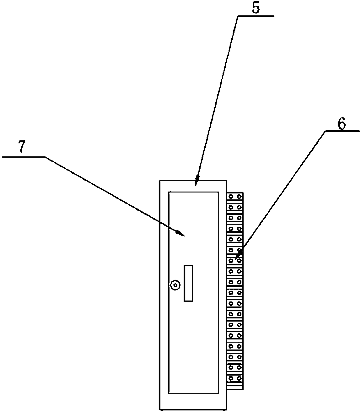
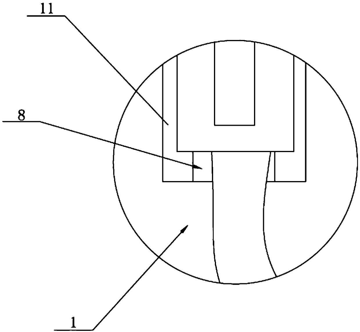
[0019] see figure 1 , figure 2 , image 3 with Figure 4 , a charging pile with rain-shielding function disclosed in the present invention, comprising a charging pile body 1, a base 2 is fixedly arranged at the lower end of the charging pile body 1, and an anti-collision plate 3 is fixedly arranged at the front end of the base 2 , the front end surface of the anti-collision plate 3 is fixedly bonded with a cushion pad 4; the rear end surface of the charging pile body 1 is fixedly provided with a battery box 5, and the rear end surface of the battery box 5 is fixedly provided with an aluminum radiator board 6, a side door 7 is provided on one side of the battery box 5, and the side door 7 is hinged to the battery box 5; a charging gun placement slot 11 is provided on the left and right sides of the charging pile body 1, and the A charging gun limiting device 8 is provided in the charging gun placement slot 11, and at least one cable positioning device 9 is provided on the l...


PUM


Abstract

The invention discloses a charging pile with rain shielding function, comprising a charging pile body and a base, wherein, a collision prevention plate is fixedly arranged at the front end of the base, and a cushion is fixedly bonded on the front end surface of the collision prevention plate; The rear end face of the charging pile body is fixedly provided with a battery box, the rear end face of the battery box is fixedly provided with an aluminum radiating plate, and a side door is arranged on one side of the battery box. The left and right side surfaces of the charging pile body are providedwith charging gun placing grooves, the left and right sides of the charging pile body are provided with cable positioning devices, A rechargeable battery is arranged in the battery box, a rechargeable cable is pierced in the cable hole of the battery box, the rechargeable cable is welded with an vehicle rechargeable gun, a solar cell panel is detachably installed on the positioning plate of the solar cell panel, a first cable is fixedly arranged on the lower end face of the solar cell panel, and a voltage transformer is connected on the first cable. The technical scheme has the advantages ofreasonable structure design, simple structure, multiple functions, good heat dissipation performance of the battery, tidy placement of the charging gun, convenient use and good practicability.

Description

technical field [0001] The invention relates to the technical field of charging piles, in particular to a charging pile with a rain-shielding function. Background technique [0002] An electric vehicle refers to a vehicle powered by a vehicle-mounted power supply, driven by a motor to drive the wheels, and conforming to the requirements of road traffic and safety regulations. Its composition includes: electric drive and control system, mechanical system such as driving force transmission, and working device to complete the predetermined task. Due to its smaller impact on the environment than traditional cars, its prospects are widely optimistic, but the current technology is still immature. With the development of electric vehicle technology, especially the country's continuous increase in air pollution control, electric vehicles, one of the best alternatives to traditional power vehicles, are developing rapidly. The charging system provides energy supply for the operation...

Claims


Application Information

Patent Timeline
Patent Type & Authority Applications(China)
IPC IPC(8): B60L53/30B60L53/302H05K7/20
CPCB60L2250/16H05K7/209Y02T10/70Y02T10/7072Y02T90/12
Inventor 王新伙
Owner ZHEJIANG KANDI SMART BATTERY SWAP TECH CO LTD
Why Eureka
Try Eureka