Sandbag filling device for physical exercise

A filling device and technology for physical exercise, which is applied in the field of sandbag filling devices for physical exercise, and can solve the problems of inconvenient use and inability to realize automatic transportation of sandbags, etc.

Active Publication Date: 2019-01-18
浦江县颐硕科技开发有限公司
View PDF9 Cites 2 Cited by
  • Summary
  • Abstract
  • Description
  • Claims
  • Application Information

AI Technical Summary

Problems solved by technology

[0002] For example, the patent number is CN201710984673.9, a kind of bagging equipment for sandbags for physical exercise, including a base plate, a vertical bar, a horizontal plate, a vertical plate, a driving mechanism, etc.; There is a horizontal plate, the driving mechanism is provided on the right side of the top of the horizontal plate, the vertical plate is symmetrically arranged in the middle of the top of the horizontal plate, the screening mechanism is provided on the top of the vertical plate, and the upper left side of the right vertical bar is provided with a feeding mechanism, but the invention The disadvantage is that when the sandbags are filled, the sandbags need to be taken out manually, which is not very convenient to use, and the automatic transportation of the sandbags cannot be realized

Method used


Image

  • Sandbag filling device for physical exercise
  • Sandbag filling device for physical exercise
  • Sandbag filling device for physical exercise

Examples


specific Embodiment approach 1

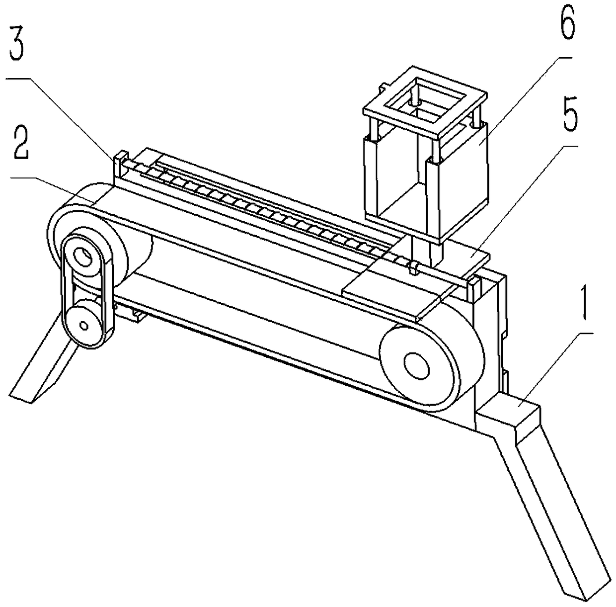
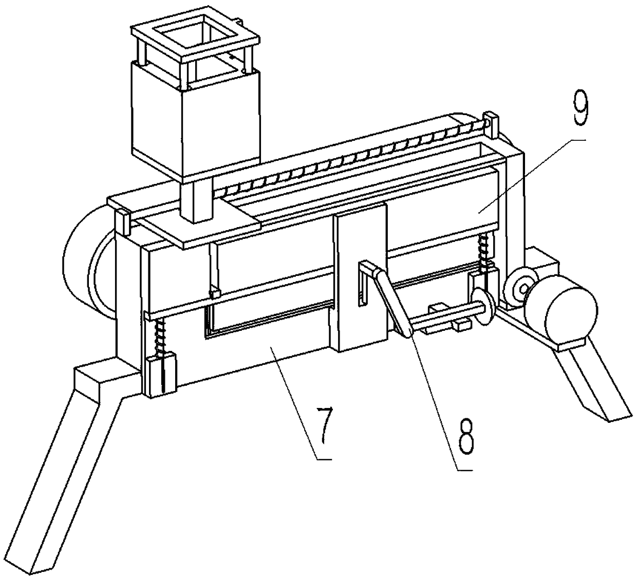
[0041] Combine below Figure 1-21 Description of this embodiment, a sandbag filling device for physical exercise, including a bracket outer frame assembly 1, a timing belt assembly 2, a spring push rod assembly 3, a load-bearing push rod assembly 5, a fixed outer frame assembly 6, a rear Side wall plate 7, push rod transmission combination 8 and sliding pressure rod combination 9, the left and right ends of the synchronous belt assembly 2 are respectively clearance fit connected to the left and right ends of the front end of the bracket outer frame assembly 1, and the spring push rod assembly The left and right ends of the lower end surface of the body 3 are respectively fixedly connected to the left and right ends of the upper end surface of the bracket outer frame assembly 1, and the lower end of the load-bearing push rod assembly 5 is slidably connected to the lower end of the inner wall of the bracket outer frame assembly 1, and the outer frame assembly is fixed. 6 is fixe...

specific Embodiment approach 2

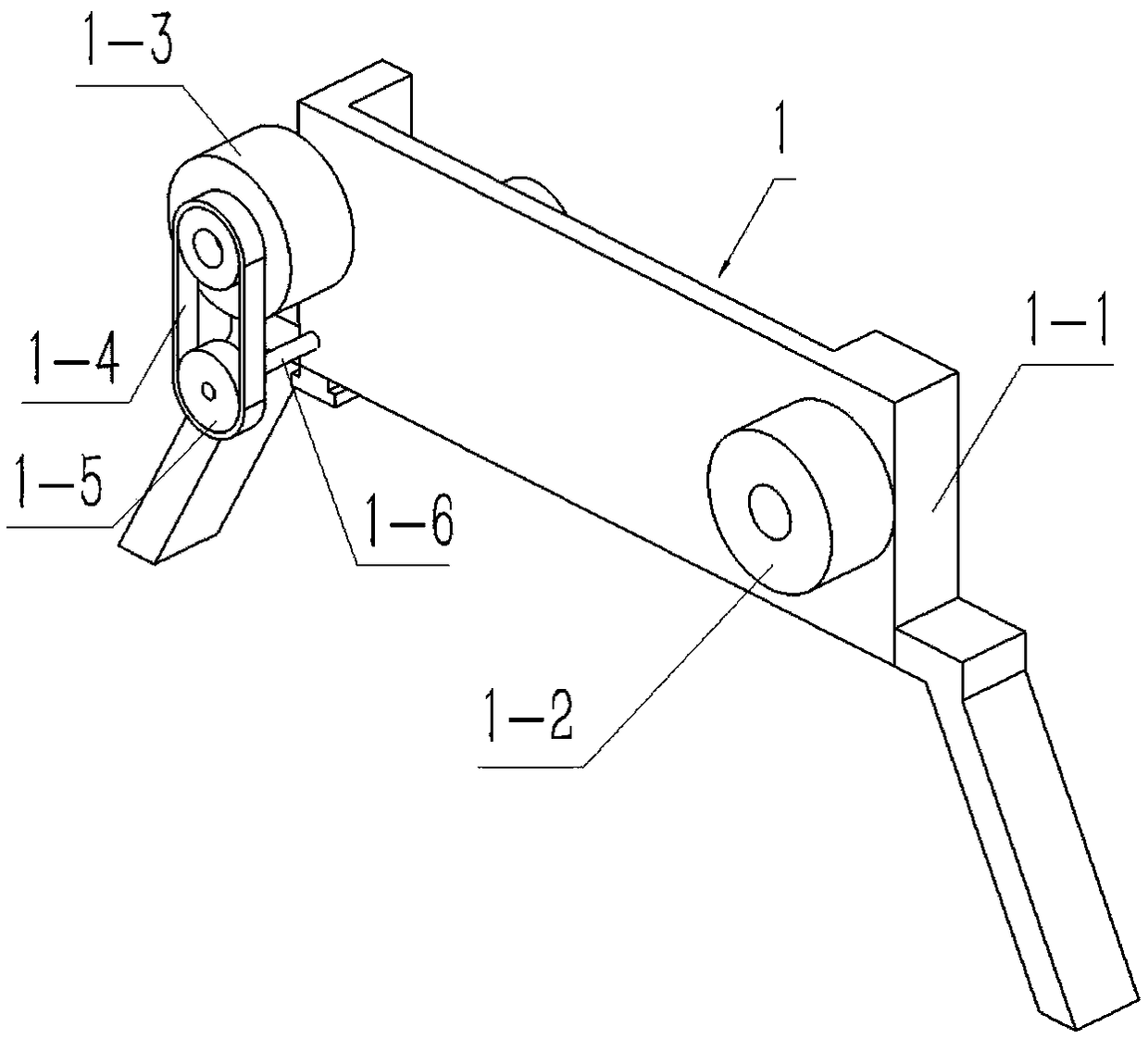
[0042] Combine below Figure 1-21 Describe this embodiment, this embodiment will further explain Embodiment 1, the bracket outer frame assembly 1 includes a bracket plate 1-1, a right rotating roller 1-2, a left rotating roller 1-3, and a transmission belt 1-4 , transmission roller 1-5, rotating shaft 1-6, motor 1-7, input bevel gear 1-8, transmission bevel gear 1-9, two brackets pushing 1-10, left rotating column 1-11, right The rotating column 1-12, the rotating hole 1-13 and the rectangular hollow cavity 1-14, the left rotating column 1-11 and the right rotating column 1-12 are respectively fixedly connected to the left and right ends of the front surface of the support plate 1-1, Rotary hole 1-13 is arranged on the left lower end of support plate 1-1 front end face, two support pushes 1-10 and is respectively fixedly connected on the left and right ends of support plate 1-1 lower end face, and the right side rotates roller 1-2 and left The side rotating rollers 1-3 are re...

specific Embodiment approach 3

[0044] Combine below Figure 1-21 Describe this embodiment, this embodiment will further explain the second embodiment, the synchronous belt assembly 2 includes a synchronous belt body 2-1 and a connecting block 2-2, and the connecting block 2-2 is fixedly connected to the synchronous belt body 2- On the outer wall of 1, the left and right ends of the inner wall of the synchronous belt body 2-1 are respectively interference fitted and connected to the left rotating roller 1-3 and the right rotating roller 1-2;

[0045] The connecting block 2-2 can be conveniently fixedly connected with the bearing sleeve 5-1.


PUM


Abstract

The invention relates to a sandbag filling device, in particular to a sandbag filling device for physical exercise. The sandbag filling device for the physical exercise has the advantages that automatic transportation of a sandbag can be achieved, the sandbag is taken out conveniently when being full, and the use is more convenient; the sandbag filling device comprises a bracket outer frame combination body, a synchronous belt combination body, a spring push rod combination body, a bearing push rod combination body, a fixed outer frame combination, a rear side wall plate, a push rod transmission combination and a sliding pressing rod combination, wherein a right side rotating roller and a left side rotating roller can be in interference fit connection with a synchronous belt body conveniently; a left side rotating column can be rotationally connected with the left side rotating roller conveniently; the right rotating roller can be rotationally connected to a right rotating column conveniently; two bracket push rods can be fixedly connected to a bracket plate conveniently, and the two bracket push rods can support the bracket plate; a connecting block can be fixedly connected with abearing sleeve conveniently; and a spring sleeve rod can be in sleeved connection with a push spring conveniently.

Description

technical field [0001] The invention relates to a sandbag filling device, in particular to a sandbag filling device for physical exercise. Background technique [0002] For example, the patent number is CN201710984673.9, a kind of bagging equipment for sandbags for physical exercise, including a base plate, a vertical bar, a horizontal plate, a vertical plate, a driving mechanism, etc.; There is a horizontal plate, the driving mechanism is provided on the right side of the top of the horizontal plate, the vertical plate is symmetrically arranged in the middle of the top of the horizontal plate, the screening mechanism is provided on the top of the vertical plate, and the upper left side of the right vertical bar is provided with a feeding mechanism, but the invention The disadvantage is that when the sandbags are filled, the sandbags need to be taken out manually, which is inconvenient to use and cannot realize the automatic transportation of the sandbags. Contents of the ...

Claims


Application Information

Patent Timeline
Patent Type & Authority Applications(China)
IPC IPC(8): B65B61/28
CPCB65B61/28
Inventor 郭子军
Owner 浦江县颐硕科技开发有限公司
Why Eureka
Try Eureka