Reaction cup feeding mechanism

A technology of reaction cup and main stirring, which is applied to conveyors, conveyor objects, transportation and packaging, etc., can solve the problems of chain drive drive mechanism occupying a large space, difficult to achieve large-scale supply in a short time, and unfavorable for user operation. , to achieve the effect of good promotion and application prospects, simple structure and small footprint

Pending Publication Date: 2019-01-18
SUZHOU INST OF BIOMEDICAL ENG & TECH CHINESE ACADEMY OF SCI
View PDF0 Cites 3 Cited by
  • Summary
  • Abstract
  • Description
  • Claims
  • Application Information

AI Technical Summary

Problems solved by technology

The chain transmission drive mechanism takes up a lot of space, which is not conducive to user operation, and the lifting efficiency of cuvettes is low, making it difficult to realize mass supply in a short time

Method used


Image

  • Reaction cup feeding mechanism
  • Reaction cup feeding mechanism
  • Reaction cup feeding mechanism

Examples


Embodiment Construction

[0027] The present invention will be further described in detail below in conjunction with the embodiments, so that those skilled in the art can implement it with reference to the description.

[0028] It should be understood that terms such as "having", "comprising" and "including" used herein do not exclude the presence or addition of one or more other elements or combinations thereof.

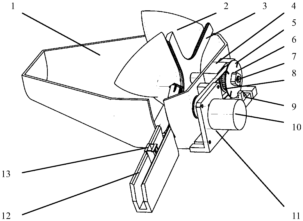
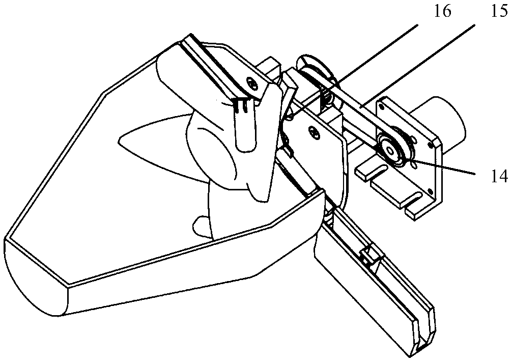
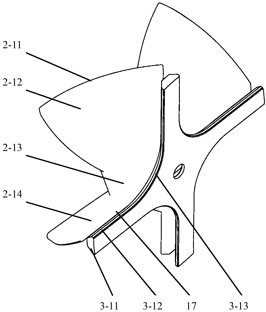
[0029] Such as Figure 1-8 As shown, a cuvette 13 feeding mechanism in this embodiment includes a rotary bin 1, a main stirring wheel 2 arranged in the rotary bin 1, a main stirring wheel 2 arranged in the rotary bin 1 and connected to one side of the main stirring wheel Auxiliary stirring wheel 3, a driving device arranged on the revolving chamber 1 and drivingly connected to the other side of the auxiliary agitating wheel 3, cuvette outlet 1-13 provided on the side of revolving chamber 1 and cuvette outlet 1-13 The ramp slideway 12 on the top; a chute 17 for accommodating the reaction cup...


PUM


Abstract

The invention discloses a reaction cup feeding mechanism, which comprises a rotary bin, a main stirring wheel arranged in the rotary bin, an auxiliary stirring wheel arranged in the rotary bin and connected with one side of the main stirring wheel, a driving device arranged on the rotary bin, and connected with the other side of the auxiliary stirring wheel, a reaction cup outlet arranged at the side part of the rotary bin and a inclined chute arranged on the outlet of the reaction cup. The reaction cup feeding mechanism is matched with the auxiliary stirring wheel through the main stirring wheel, so that the mixing reaction cup can be conveniently mixed evenly, the reaction cup can be easily held up by the stirring wheel, continuous supply is realized, the occupied volume is small, and isconvenient for users to operate; an angle is formed between a main stirring wheel blade and the rotating shaft, and forms a cavity between the rotary bin, the number of the lifting reaction cup is increased, and the probability that the reaction cup is successfully fallen into the inclined chute is improved.

Description

technical field [0001] The invention relates to the field of material transportation equipment, in particular to a reaction cup feeding mechanism. Background technique [0002] At present, most of the grasping operation of cuvettes adopts the way of chain drive lifting. The chain transmission drive mechanism takes up a lot of space, which is not conducive to user operation, and the lifting efficiency of cuvettes is low, making it difficult to realize mass supply in a short time. Contents of the invention [0003] The technical problem to be solved by the present invention is to provide a cuvette feeding mechanism for the deficiencies in the above-mentioned prior art. [0004] In order to solve the above technical problems, the technical solution adopted in the present invention is: a cuvette feeding mechanism, including a rotary bin, a main stirring wheel arranged in the rotary bin, a The auxiliary stirring wheel connected to one side of the stirring wheel, the driving d...

Claims


Application Information

Patent Timeline
Patent Type & Authority Applications(China)
IPC IPC(8): B65G47/14
CPCB65G47/1428B65G2201/0235
Inventor 刘亮王弼陡江浩罗刚银王鹏
Owner SUZHOU INST OF BIOMEDICAL ENG & TECH CHINESE ACADEMY OF SCI
Why Eureka
Try Eureka