

Novel wire winding device for power adapter
A technology of power adapter and winding device, which is applied in the direction of transportation and packaging, delivery of filamentous materials, thin material processing, etc. It can solve the problems of no fixed storage space, inconvenient use, easy damage of cables, etc., and achieves the goal of increasing The circumference of the wire can be wound, which is convenient for winding storage and reduces the effect of damage probability
- Summary
- Abstract
- Description
- Claims
- Application Information
AI Technical Summary
Problems solved by technology
Method used
Image

Examples
Embodiment 1
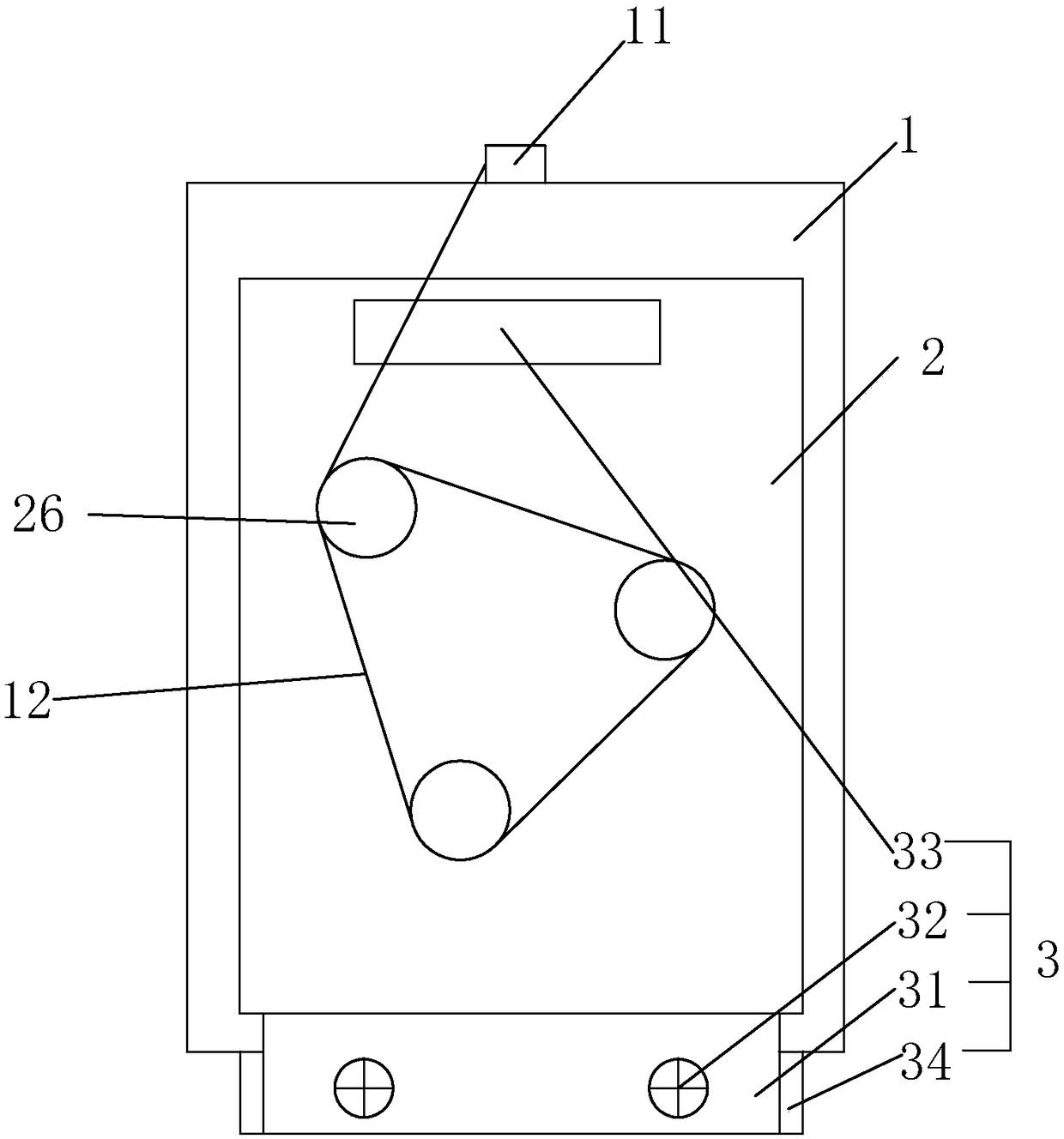
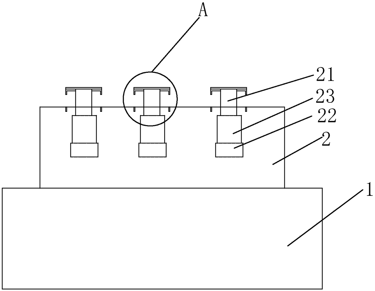
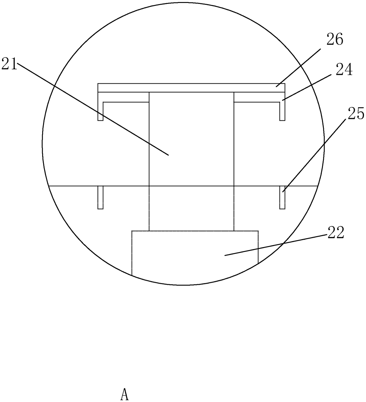
[0022] Embodiment 1: A novel winding device for power adapters, such as figure 1 with 2 As shown, the power supply 11 adapter includes a housing 1, one end of the housing 1 is connected to a power supply 11, a cable 12 is connected to the power supply 11, and a mounting shell 2 is provided on the upper surface of the housing 1, and three coils are arranged on the mounting shell 2. The wire post 21 is connected along the tangent point direction of the three winding posts 21 to form an encircling circle, which is triangular in shape, that is, the cable 12 can be wound and stored around the three winding posts 21; image 3 As shown, at the same time, three micro-drive motors 22 are fixedly installed in the installation shell 2, and the output shaft of the micro-drive motor 22 is fixedly provided with a working screw 23. Motor 22 respectively drives the up and down linear motion of three winding posts 21, and the top of winding post 21 is fixedly provided with limit plate 24, and...
Embodiment 2
[0024] Embodiment 2: A new type of winding device used on a power adapter, the difference from Embodiment 1 is that, as figure 1 As shown, the installation shell 2 realizes the connection on the housing 1 through the detachable connection mechanism 3, so that the assembly and disassembly of the winding device on the power supply 11 adapter can be realized according to actual needs. The detachable connection mechanism 3 includes a fixed installation One end of the shell 2 is away from the connection plate 31 of the power supply 11, and the end of the shell 1 away from the power supply 11 is fixed with an extension plate 34. The connection plate 31 is provided with a plurality of mounting bolts 32 connected with the extension plate 34, and the shell 2 is installed at the same time. The inside of the other end is fixedly provided with a magnet chip 33, and the housing 1 is provided with an iron core (not shown) that is adsorbed to the magnet chip 33; The limit position on the bod...
PUM
 Abstract
Description
Claims
Application Information