
Adjusting device used for assembly of aircraft wing

A technology of adjusting device and wing, applied in aircraft assembly and other directions, can solve problems such as hidden safety hazards of aircraft, damage to aircraft wing structure, large difference in wing volume and height, etc., to reduce the number of handling times and the operation process is fast Efficient and favorable for transportation and transfer

Active Publication Date: 2019-10-22
XIAN AERONAUTICAL UNIV
View PDF6 Cites 0 Cited by
  • Summary
  • Abstract
  • Description
  • Claims
  • Application Information

AI Technical Summary

Problems solved by technology

The volume and height of the wings of these aircraft are quite different. When transferring and assembling the wings, it is easy to damage the wing structure of the aircraft due to improper operation, resulting in potential safety hazards for the aircraft.

Method used


Image

  • Adjusting device used for assembly of aircraft wing
  • Adjusting device used for assembly of aircraft wing
  • Adjusting device used for assembly of aircraft wing

Examples


Embodiment 1

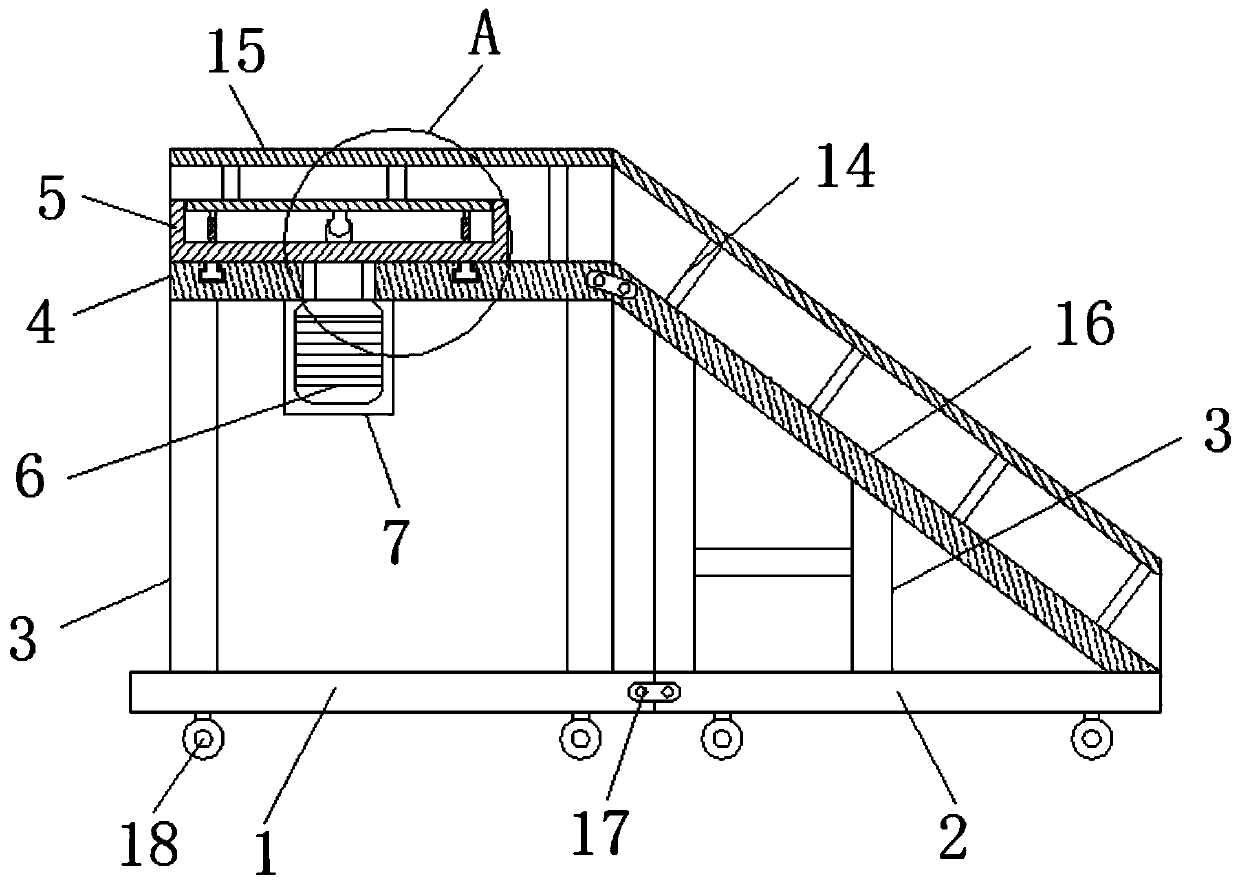
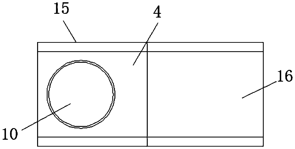
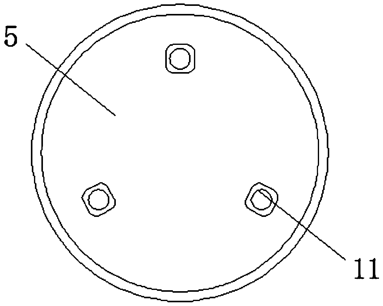
[0044] like Figure 1-4 As shown in the figure, an adjusting device for assembling an aircraft wing includes a base plate 1 of a mounting frame and a base plate 2 of a lifting frame, an operation platform 4 is arranged above the base plate 1 of the installation frame through a support column 3, and an operation platform 4 is arranged below the operation platform 4 There is a motor frame 7, a motor 6 is arranged in the motor frame 7, a base 5 is arranged above the operation platform 4, and the symmetrical center of the lower end of the base 5 is fixedly connected with one end of the output shaft of the motor 6, which is controlled by the motor 6 The base 5 is rotated to realize the adjustment of the direction of the adjusting device when the aircraft wing is assembled. The upper end of the base 5 is sleeved with an operation panel 10, and at least three sets of mutually symmetrical hydraulic cylinders 11 are arranged between the operation panel 10 and the base 5. Adjustment of...

Embodiment 2

[0055] like Figure 1-4 As shown in the figure, an adjusting device for assembling an aircraft wing includes an installation frame base plate 1 and a lifting frame base plate 2, an operation platform 4 is provided above the installation frame base plate 1 through a support column 3, and an operation platform 4 is arranged below the operation platform 4. There is a motor frame 7, a motor 6 is arranged in the motor frame 7, a base 5 is arranged above the operation platform 4, and the symmetrical center of the lower end of the base 5 is fixedly connected with one end of the output shaft of the motor 6, which is controlled by the motor 6 The base 5 is rotated to adjust the direction of the aircraft wing; the upper end of the base 5 is sleeved with an operation panel 10, and at least three sets of mutually symmetrical hydraulic cylinders 11 are arranged between the operation panel 10 and the base 5. Adjusting the hydraulic cylinder 11 realizes the adjustment of the inclination angl...


PUM

PropertyMeasurementUnit
Longitudinal modulus of elasticityaaaaaaaaaa
Specific surface areaaaaaaaaaaa
Hardnessaaaaaaaaaa

Abstract

The invention discloses an adjusting device used for assembly of an aircraft wing. The adjusting device comprises an installation rack bottom plate and a lifting rack bottom plate. The upper part of the installation rack bottom plate is provided with an operation platform by a supporting column, and the lower part of the operation platform is provided with a motor rack. A motor is disposed in themotor rack, and the device is used to convey the aircraft wing through the lifting rack by using a transport vehicle directly to the operation platform of the installation rack, and therefore the transport times of the aircraft wing can be reduced, damage possibility can be reduced, and therefore the adjustment of the direction angle of the aircraft wing can be realized, and the whole operation process is fast and efficient, and then the aircraft wing of the operation panel can maintain stable, and the installation rack and the lifting rack can be connected by a locking buckle, thereby facilitating dismounting, and facilitating the transport of the device.

Description

technical field [0001] The invention belongs to the technical field of tooling for assembling wings, in particular to an adjusting device for assembling aircraft wings. Background technique [0002] The aircraft wing is one of the important parts of the aircraft, which is installed on the fuselage. Its main function is to generate lift, and at the same time, ammunition compartments and fuel tanks can be arranged in the wings, and the landing gear can be stored during flight. In addition, flaps to improve take-off and landing performance and ailerons for lateral control of the aircraft are also installed on the wings, and some are also equipped with slats and other devices to increase lift on the leading edge of the wing. [0003] In the process of aircraft wing assembly, it is necessary to strictly ensure the installation and connection dimensions and tolerance ranges of various components between the aircraft wing and the fuselage. However, due to the large number of airc...

Claims


Application Information

Patent Timeline
IPC IPC(8): B64F5/10
CPCB64F5/10
Inventor 赵东平郭温张建华侯伟
Owner XIAN AERONAUTICAL UNIV
Learn More