Hydraulic oscillator

A hydraulic oscillator and water channel technology, which is applied to vibration drilling, vibration generating devices, wellbore/well components, etc., can solve the problems of high pressure consumption of screw tools and difficult valve replacement, and achieves simple structure, convenient replacement, The effect of convenient transportation

Active Publication Date: 2019-01-18
SINOPEC OILFIELD EQUIP CORP +1
View PDF6 Cites 7 Cited by
  • Summary
  • Abstract
  • Description
  • Claims
  • Application Information

AI Technical Summary

Problems solved by technology

[0003] An object of the present invention is to provide a hydraulic oscillator, which not only solves the problem of high pr

Method used


Image

  • Hydraulic oscillator
  • Hydraulic oscillator
  • Hydraulic oscillator

Examples


Embodiment Construction

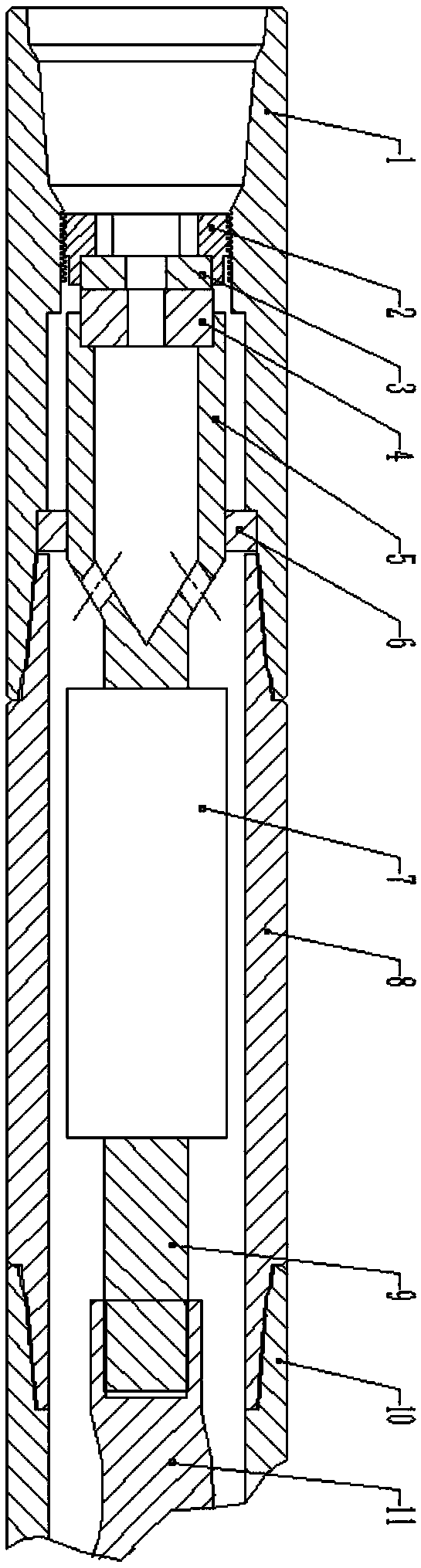
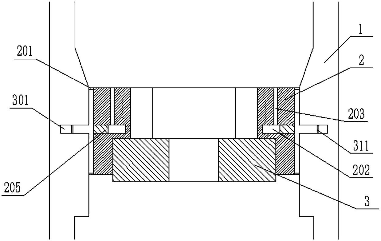
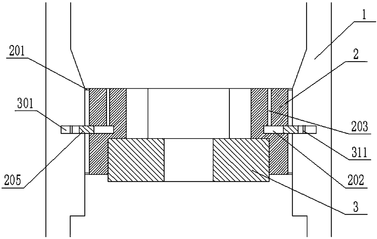
[0027] The present invention will be further described in detail below in conjunction with the accompanying drawings, so that those skilled in the art can implement it with reference to the description.

[0028] It should be noted that the experimental methods described in the following embodiments, unless otherwise specified, are conventional methods, and the reagents and materials, if not otherwise specified, can be obtained from commercial sources; in the description of the present invention, The terms "landscape", "portrait", "top", "bottom", "front", "rear", "left", "right", "vertical", "horizontal", "top", "bottom", The orientation or positional relationship indicated by "inner", "outer", etc. is based on the orientation or positional relationship shown in the drawings, which is only for the convenience of describing the present invention and simplifying the description, and does not indicate or imply that the referred device or element must have Certain orientations, co...


PUM


Abstract

The invention discloses a hydraulic oscillator, which comprises a sleeve with a hollow structure, wherein the upper end of the sleeve is connected with an upper joint and the lower end of the sleeve is connected with a screw stator; the upper joint is also of a hollow structure and the axes of the sleeve, the screw stator and the upper joint coincide; the upper end of the screw rotor is connectedwith the lower end of a universal shaft through a connecting rod, and the universal shaft is positioned in the sleeve; a movable valve is fixed by a movable valve seat and positioned in that upper joint, the low end of the movable valve seat is connected with the upper end of the universal shaft, the movable valve seat has a hollow structure and is also provided with a plurality of channels communicate with the space between the sleeve and the universal shaft, and the movable valve is provided with a plurality of flow passage holes; the static valve is positioned above the movable valve and connected to the inner wall of the upper joint through a static valve seat, the static valve is also provided with a flow passage hole, and the static valve is tightly attached to the movable valve. Thehydraulic oscillator not only solves the problem of high pressure consumption of a hydraulic pulse generating screw tool, but also solves the problem that the valve is difficult to replace.

Description

technical field [0001] The invention relates to the technical field of hydraulic pulse speed-increasing tools for oil wells. More specifically, the present invention relates to hydraulic oscillators. Background technique [0002] Most of the existing hydraulic pulse speed-increasing tools use the screw as the power to drive the movement of the valve, thereby controlling the opening and closing of the drilling fluid flow channel to generate pressure pulses. The pressure loss of the tool has two parts: 1. The pressure loss of the screw (0.5-0.8MPa); 2. The pressure loss of the valve (1.5-2MPa); the pressure loss of the valve is an active and beneficial pressure loss, which is mainly used used to generate impact. The pressure loss of the screw is a kind of harmful pressure loss. The lower the pressure loss of the screw, the better it can ensure the volumetric efficiency of the motor and the movement of the drive valve! The on-site control of pressure loss is very strict, and...

Claims


Application Information

Patent Timeline
IPC IPC(8): E21B7/24E21B28/00
CPCE21B7/24E21B28/00
Inventor 潘灵永钱伟强余长柏蒋洪亮类歆李大彬
Owner SINOPEC OILFIELD EQUIP CORP
Why Eureka
Try Eureka