Vertical multi-ejection-tube type three-ring fire burner

A burner and ejector technology, which is applied to burners, gas fuel burners, combustion methods, etc., can solve the problems of low power, inconvenient power adjustment, and low energy efficiency.

Pending Publication Date: 2019-01-18
曾祥林
View PDF0 Cites 1 Cited by
  • Summary
  • Abstract
  • Description
  • Claims
  • Application Information

AI Technical Summary

Problems solved by technology

The existing problems are: low power, insufficient combustion, low energy efficiency, and inconvenient power adjustment

Method used


Image

  • Vertical multi-ejection-tube type three-ring fire burner
  • Vertical multi-ejection-tube type three-ring fire burner
  • Vertical multi-ejection-tube type three-ring fire burner

Examples


Embodiment 1

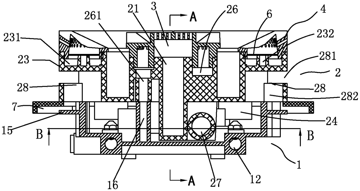
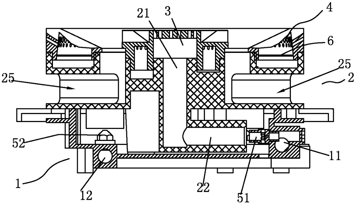
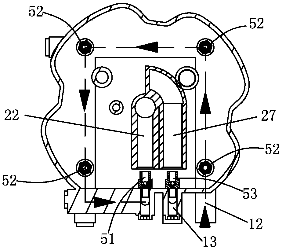
[0047] Such as figure 1 , figure 2 , image 3 As shown, a vertical multi-injection tube type three-ring fire burner includes a base 1 with an upper opening, a fire distributor seat 2, a central fire cover 3 and an outer ring fire cover 4, and the front wall of the base 1 is provided with Center air inlet 11, the outlet end of center air inlet 11 is provided with center nozzle 51, and the axis of center nozzle 51 is parallel with horizontal plane, and the base plate of base 1 is provided with the outer ring air inlet 12 of the frame of front opening, sets Some air outlet seats with the outer ring air inlet channel 12 in the base 1 are provided with an outer nozzle 52 on the air outlet seat; the fire distribution seat 2 includes a central fire cover seat 21, a center ejector pipe 22 communicated with the central fire cover seat, An annular seat 23 with an outer ring gas groove 231 , several axially outer injection pipes 24 and radial secondary air passages 25 communicated wit...

Embodiment 2

[0067] Such as Figure 8 , Figure 10 , Figure 12 , Figure 13 As shown, the axis of the inner injection pipe 27 is perpendicular to the horizontal plane;

[0068] The inner ring air inlet passage 13 extends into the base 1, and the inner nozzle 53 is arranged at the air outlet, and the axis of the inner nozzle 53 is perpendicular to the horizontal plane.

Embodiment 3

[0070] Such as Figure 14 , Figure 15 , Figure 16 As shown, the base 1 is wave-shaped, and the base 1 is provided with a wave-shaped interface 14 and a seat plate 15 surrounding the upper opening. The seat plate 15 at the trough 142 is provided with a connection hole for a liquid-receiving tray or a cooker panel connect;

[0071] The axis of the inner injection pipe 27 is parallel to the horizontal plane;

[0072] The air outlet end of the inner ring air inlet channel 13 is positioned on the inwall of the base 1, and the axis of the inner nozzle 53 at the air outlet end is parallel to the horizontal plane;

[0073] The lower end surface of the fire distributor seat 2 is provided with a counterbore 29;

[0074] The wave-shaped interface 14 is inserted into the counterbore 29; there is a gap between the lower end surface of the firearm seat 2 and the seat plate 15.


PUM


Abstract

The invention provides a vertical multi-ejection-tube type three-ring fire burner. The vertical multi-ejection-tube type three-ring fire burner comprises a base with an upper opening, a distributor seat, a central fire cover and an outer ring fire cover, the distributor seat is further provided with an inner ring-shaped fuel gas groove with an upper opening and an inner ejection tube; the centralfire cover is further provided with an inner ring-shaped combustion chamber, with a lower opening, surrounding the central fire cover, a top plate of the central fire cover is provided with a centralcombustion hole, and an outer ring wall plate of the inner ring-shaped combustion chamber is provided with an inner ring combustion hole; the base is further provided with an inner ring air inlet passage, and an air outlet end of the inner ring air inlet passage is provided with an inner nozzle; the inner ring-shaped combustion chamber is matched with the inner ring-shaped fuel gas groove, and theinner nozzle corresponds to the inner ejection tube; a one-time air passage is communicated with an inner cavity of the base; and a central air inlet passage is communicated with the tail end of an outer ring air inlet passage or an air source of the central air inlet passage. Due to adopting the structure, the arrangement of the inner ring-shaped combustion chamber increases power, the adjustment of the power is convenient, and the energy efficiency is improved.

Description

technical field [0001] The invention relates to a stove burner. Background technique [0002] The current existing technology includes a base with an upper opening, a fire distribution seat, a central fire cover and an outer ring fire cover. The wall plate at the front of the base is provided with a central air inlet, and the central air intake extends from the wall plate to the center of the base. There is a central nozzle at the air outlet end, the axis of the central nozzle is perpendicular to the horizontal plane, the outer ring air inlet of the front-opening frame is arranged on the bottom plate of the base, and several air outlet seats are arranged in the base and the outer ring air inlet passage, The outlet seat is provided with an outer nozzle; the firearm seat includes a central fire cover seat, a central injection pipe connected with the central fire cover seat, a circular seat with an outer ring gas groove, and a number of axial nozzles connected with the outer ri...

Claims


Application Information

Patent Timeline
IPC IPC(8): F23D14/02F23D14/58
CPCF23D14/02F23D14/58F23D2900/14062
Inventor 曾祥林
Owner 曾祥林
Why Eureka
Try Eureka