Pressure sensor using fiber Bragg grating

A technology of pressure sensor and optical fiber grating, which is applied in the field of pressure sensor using optical fiber grating, can solve the problems that the pressure value cannot be collected and transmitted, the difficulty of electronic pressure sensor, the long distance of wiring signal transmission of environmental electromagnetic interference sensor, etc., to achieve accurate measurement value effect

Pending Publication Date: 2019-01-18
XIAMEN UNIV
View PDF6 Cites 0 Cited by
  • Summary
  • Abstract
  • Description
  • Claims
  • Application Information

AI Technical Summary

Problems solved by technology

The pressure can only be roughly read through the rotation of the pointer, and the pressure value cannot be collected and transmitted; the signal of the electronic pressure sensor needs to be collected and transmitted by the corresponding circuit. In the case of complex wiring, flammable and explosive environments, and long signal transmission distances, electronic pressure sensors have great difficulties in practical applications.

Method used


Image

  • Pressure sensor using fiber Bragg grating
  • Pressure sensor using fiber Bragg grating

Examples


Embodiment Construction

[0012] The following embodiments will further illustrate the present invention in conjunction with the accompanying drawings.

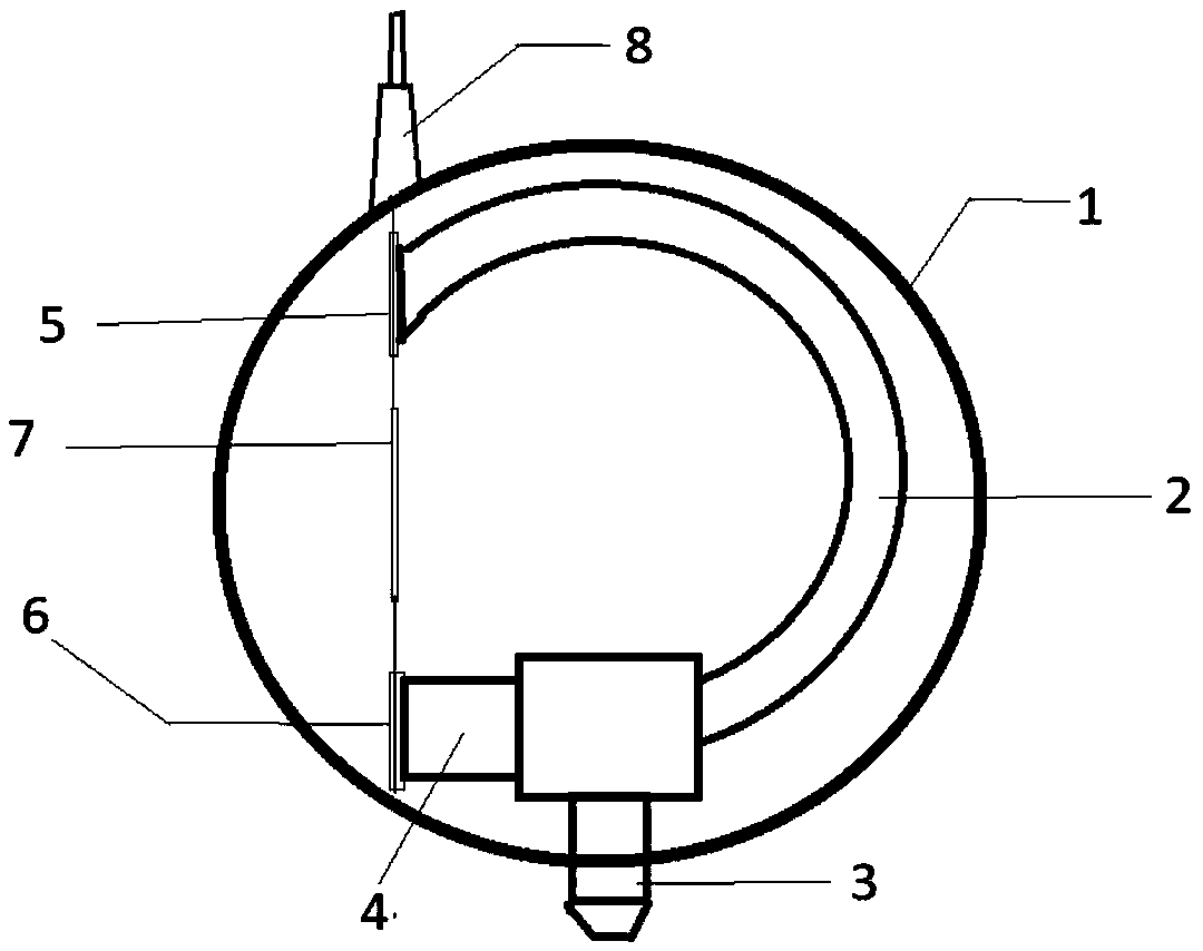
[0013] Such as figure 1 and 2 As shown, the embodiment of the present invention is provided with a sensor protective case 1, a copper hollow elbow 2, an M14×1.5 pipe interface 3, a copper metal block 4, an upper metal protective cover 5, a lower metal protective cover 6, an optical fiber cloth Grid grating 7 and optical fiber protective cover 8; the sensor protective shell 1 is set on the copper hollow elbow 2, the pipe interface 3, the copper metal block 4, the upper metal protective cover 5, the lower metal protective cover 6 and the optical fiber Bragg On the outer periphery of the grating 7, the copper hollow elbow 2 is connected to the pipe interface 3, and the upper metal protection sleeve 5 and the lower metal protection sleeve 6 are respectively connected to the end of the copper hollow elbow 2 and the copper metal block 4; The Rag grating 7...


PUM


Abstract

The invention discloses a pressure sensor using a fiber Bragg grating, and relates to a pressure sensor. The pressure sensor is provided with a sensor protective shell, a copper hollow elbow, a pipeline interface, a copper metal block, an upper metal protective sleeve, a lower metal protective sleeve, a fiber Bragg grating and an optical fiber protective sleeve, wherein the sensor protective shellis arranged on the peripheries of the copper hollow elbow, the pipeline interface, the copper metal block, the upper metal protective sleeve, the lower metal protective sleeve and the fiber Bragg grating; the copper hollow elbow is connected with the pipeline interface; the upper metal protective sleeve and the lower metal protective sleeve are connected with a tail end of the copper hollow elbowand the copper metal block respectively; the fiber Bragg grating is connected with an upper port of the copper hollow elbow and one end of the copper metal block respectively; and the optical fiber protective sleeve is arranged on the top of the sensor protective shell. Through the non-sticking scheme, the linear change of the central wavelength of the grating in a strain process can be better ensured in order to obtain more accurate measurement values.

Description

technical field [0001] The invention relates to a pressure sensor, in particular to a pressure sensor using an optical fiber grating that changes the strain of the optical fiber grating through changes in liquid or gas pressure. Background technique [0002] The fiber grating is realized by introducing periodic refractive index changes in the core region of the fiber by ultraviolet laser irradiation. When the change period of the refractive index in the core area of ​​the single-mode fiber is small, the fundamental mode of the forward transmission can be coupled with the fundamental mode of the backward transmission and transfer most of the power. This kind of fiber grating is called fiber Bragg grating (fiber Bragg grating, FBG) grating, and the wavelength of light satisfying this energy conversion or resonance is called the Bragg wavelength of the fiber Bragg grating, or the center wavelength of the fiber Bragg grating. [0003] The traditional gas or liquid pressure meas...

Claims


Application Information

Patent Timeline
Patent Type & Authority Applications(China)
IPC IPC(8): G01L11/02
CPCG01L11/025
Inventor 董小鹏丁仕祺关云卿卢丽华
Owner XIAMEN UNIV
Why Eureka
Try Eureka