Optical fiber grating soil pressure sensor

An earth pressure sensor and optical fiber grating technology, which is applied in the field of earth pressure applications, can solve the problems that the earth pressure sensor cannot eliminate the influence of temperature, reduce the authenticity of measurement results, and cannot realize distributed measurement, etc., and achieves low cost, simple structure, and convenient cascade effect

Inactive Publication Date: 2010-08-11
CHANGAN UNIV
View PDF0 Cites 0 Cited by
  • Summary
  • Abstract
  • Description
  • Claims
  • Application Information

AI Technical Summary

Problems solved by technology

[0002] Traditional earth pressure sensors cannot exclude the influence of temperature, the measurement accuracy is low, and distributed measurement cannot be realized
However, in the existing fiber grating earth pressure sensor, the grating is pasted on the elastic plate. The force curve of the grating is not linear but a parabola, which will cause the distortion of the wavelength of the grating. body noise, affecting the measurement results
[0003] Although in terms of temperature compensation, the existing fiber grating sensor is also pasted on the same material, this method cannot avoid errors caused by the pasting process and pasting materials, and will also reduce the authenticity of the measurement results

Method used


Image

  • Optical fiber grating soil pressure sensor
  • Optical fiber grating soil pressure sensor

Examples


Embodiment Construction

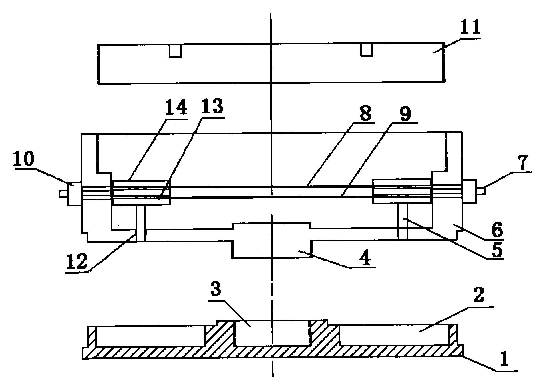
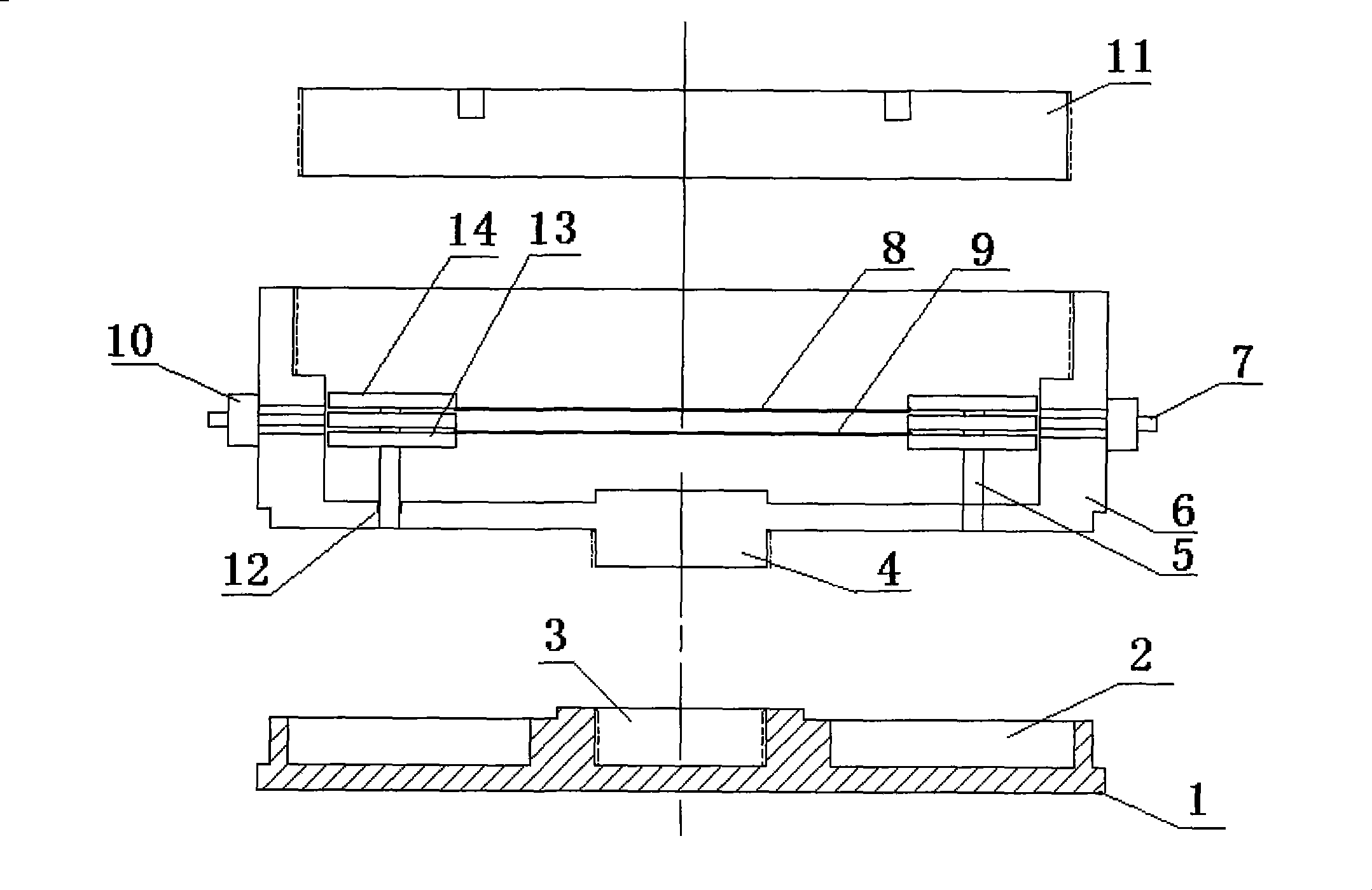
[0019] As shown in Figure 1, it includes a pressure bearing plate 1, a disc cover 11 and a circular cavity housing 6, the pressure bearing plate 1 and the circular cavity housing 6 are connected by threads, and the circular cavity housing 6 and the disc cover 11 are used Threaded connection; two wedge-shaped blind holes 12 are symmetrically opened at the bottom of the round cavity shell 6, and the two fixing columns 5 are wedged into the two wedge-shaped blind holes 12. The upper part of the fixed column 5 has a solid splint 13 and a buffer splint 14. The two symmetrical solid splints 13 are used to fix the two ends of the force-measuring grating 9, and the symmetrical buffer splint 14 is used to fix the two ends of the temperature compensation grating 8. The force-measuring grating 9 is connected in series with the temperature compensation grating 8, and after the force measuring grating 9 and the temperature compensation grating 8 are connected in series, the two ends are con...


PUM


Abstract

The invention belongs to an optical fiber grating earth pressure sensing method. The method is characterized in that: a bearing disc (1) is connected with a cylindrical cavity shell (6), the cylindrical cavity shell (6) is connected with a disc cover (11); the bottom end of the cylindrical cavity shell (6) is provided with two wedge-shaped blind holes (12), and two fixed legs (5) are wedged into the two wedge-shaped blind holes (12); the fixed legs (5) are provided with fixed splints (13) and buffer splints (14) respectively, the fixed splints (13) are fixed at the two ends of a force measurement grating (9), the buffer splints (14) are fixed at the two ends of a temperature compensation grating (8), after the force measurement grating (9) and the temperature compensation grating (8) are connected in series, the two ends of the connected force measurement grating (9) and the temperature compensation grating (8) are connected with an input / output optical fiber (7) by a grating port (10), wavelength values of the force measurement grating (9) and the temperature compensation grating (8) are measured by an optical fiber grating demodulator, and then a true value of the earth pressureis obtained by subtracting the wavelength value of the temperature compensation grating (8) from the wavelength value of the force measurement grating (9). The method has the advantages of high sensitivity, anti-electromagnetic interference, good stability and being capable of monitoring landslide mass deformation, subgrade settlement, tunnel roof deformation and bridge deformation for a long time.

Description

technical field [0001] The invention belongs to the field of application of fiber grating sensing to earth pressure in buildings, bridges, landslides, etc., and is specifically a fiber grating earth pressure sensor. Background technique [0002] Traditional earth pressure sensors cannot rule out the influence of temperature, have low measurement accuracy, and cannot realize distributed measurement. In the existing fiber grating earth pressure sensor, the grating is pasted on the elastic plate, and the force curve of the grating is not linear but a parabola, which will cause the distortion of the wavelength of the grating. The body noise affects the measurement results. [0003] Although in terms of temperature compensation, the existing fiber grating sensor is also pasted on the same material, this method cannot avoid errors caused by the pasting process and pasting materials, and will also reduce the authenticity of the measurement results. Contents of the invention [...

Claims


Application Information

Patent Timeline
Patent Type & Authority Patents(China)
IPC IPC(8): G01L1/24G01B11/16
Inventor 胡志新马云宾陈朋超李宁孙异李俊
Owner CHANGAN UNIV
Why Eureka
Try Eureka