
Device and method for online corrosion measurement during chemical cleaning of boiler tube

A measuring device, chemical cleaning technology, applied in the direction of measuring devices, weather resistance/light resistance/corrosion resistance, scientific instruments, etc., can solve the problems of corroding boiler tubes, affecting the thermal efficiency of boilers, and being unable to accurately judge fouling and cleaning, and achieve reduction effect of possibility

Pending Publication Date: 2019-01-18
GUODIAN NANJING ELECTRIC POWER TEST RES CO LTD
View PDF0 Cites 2 Cited by
  • Summary
  • Abstract
  • Description
  • Claims
  • Application Information

AI Technical Summary

Problems solved by technology

[0002] Boiler tubes used in power stations will form an oxide layer on the inner and outer heating surfaces after long-term use, that is, scaling, which affects the thermal efficiency of the boiler. Regular chemical cleaning methods are required to remove scaling. At present, electrochemical corrosion potential ECP can be used monitoring technology, electrochemical impedance spectroscopy monitoring technology, electrochemical noise monitoring technology and resistance probe monitoring technology to monitor the cleaning process, but none of the above methods can accurately judge whether the scale is properly cleaned, resulting in the early or late end of the cleaning process , there is incomplete cleaning of scale deposits or corrosion of boiler tubes

Method used


Image

  • Device and method for online corrosion measurement during chemical cleaning of boiler tube

Examples


Embodiment

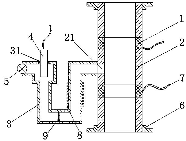
[0021] Such as figure 1 As shown, an on-line corrosion measuring device for a boiler tube chemical cleaning process of the present invention includes several insulating rings 2, at least one annular electrode 1 and a U-shaped metal tube 3. In this embodiment, the insulating ring 2 There are three, and there are two ring electrodes 1. The insulating ring 2 is made of corrosion-resistant polytetrafluoroethylene. The ring electrode is made by cutting the boiler tube to be measured. The inner diameter and outer diameter of the insulating ring 2 are the same 1, the insulating ring 2 and the ring-shaped electrode 1 are arranged at intervals, and the connection is fixed and bonded by anti-corrosion glue, and kept sealed, so that it forms a connected tubular measuring device. The inner and outer walls of the tubular measuring device are smoothly connected, and the tubular The two ends of the measuring device are fixedly provided with flanges 6, and are connected to the cut-off boiler ...


PUM


Abstract

The invention relates to a device for online corrosion measurement during chemical cleaning of a boiler tube. The device comprises a first measurement device and a second measurement device, wherein the first measurement device and the second measurement device each comprise a plurality of insulation rings, at least one annular electrode, and a U-shaped metal tube; the insulation rings and the corresponding annular electrode are arranged in a spaced manner and fixedly and hermetically connected to form each communicated tubular measurement device; the two ends of each tubular measurement device are connected with the boiler tube to be cleaned through flanges; a through hole is formed in the side wall of one insulation ring in each tubular measurement device; one end of each metal tube is communicated with the corresponding through hole, and a reference electrode is arranged at the other end of each metal tube; the annular electrode in the first measurement device is made of the boilertube to be cleaned; and the annular electrode in the second measurement device is made of a boiler tube without scale, of which the material is the same as that of the boiler tube to be cleaned. The device provided by the invention has the advantages that the boiler tube to be cleaned is used as the measurement electrode, so that an electrode cleaning progress is identical to a boiler tube cleaning progress; and through the comparison measurement device, that is, the boiler tube without the scale in the second annular electrode, the time at which the scale is completely cleaned off can be accurately judged.

Description

technical field [0001] The invention relates to a detection device and method, in particular to an on-line corrosion measurement device and method in the chemical cleaning process of a power plant boiler. Background technique [0002] Boiler tubes used in power stations will form oxide layers on the inner and outer heating surfaces after long-term use, that is, scaling, which affects the thermal efficiency of the boiler. Regular chemical cleaning methods are required to remove scaling. At present, electrochemical corrosion potential ECP monitoring technology, electrochemical impedance spectroscopy monitoring technology, electrochemical noise monitoring technology and resistance probe monitoring technology to monitor the cleaning process, but none of the above methods can accurately judge whether the scale is properly cleaned, resulting in the early or late end of the cleaning process , there is incomplete cleaning of fouling or corrosion of boiler tubes. Contents of the in...

Claims


Application Information

Patent Timeline
IPC IPC(8): G01N17/02G01N17/00
CPCG01N17/008G01N17/02
Inventor 李洪峰薛庆堂聂新辉韩松
Owner GUODIAN NANJING ELECTRIC POWER TEST RES CO LTD
Learn More