
XRF detector

A detector and detector technology, applied in the field of XRF detectors, can solve the problems of bulky, bulky, inconvenient soil detection and analysis, etc.

Pending Publication Date: 2019-01-18
和辰(深圳)科技有限公司
View PDF0 Cites 4 Cited by
  • Summary
  • Abstract
  • Description
  • Claims
  • Application Information

AI Technical Summary

Problems solved by technology

[0004] Based on this, it is necessary to provide an XRF detector for the problem that the desktop X-ray fluorescence spectrometer in the prior art is large and heavy, and it is not convenient for inspectors to directly detect and analyze the soil on site.

Method used


Image

  • XRF detector
  • XRF detector
  • XRF detector

Examples


Embodiment Construction

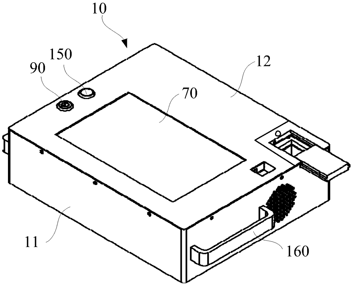
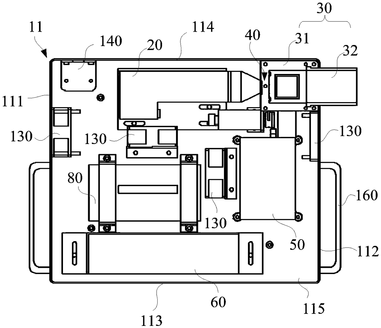
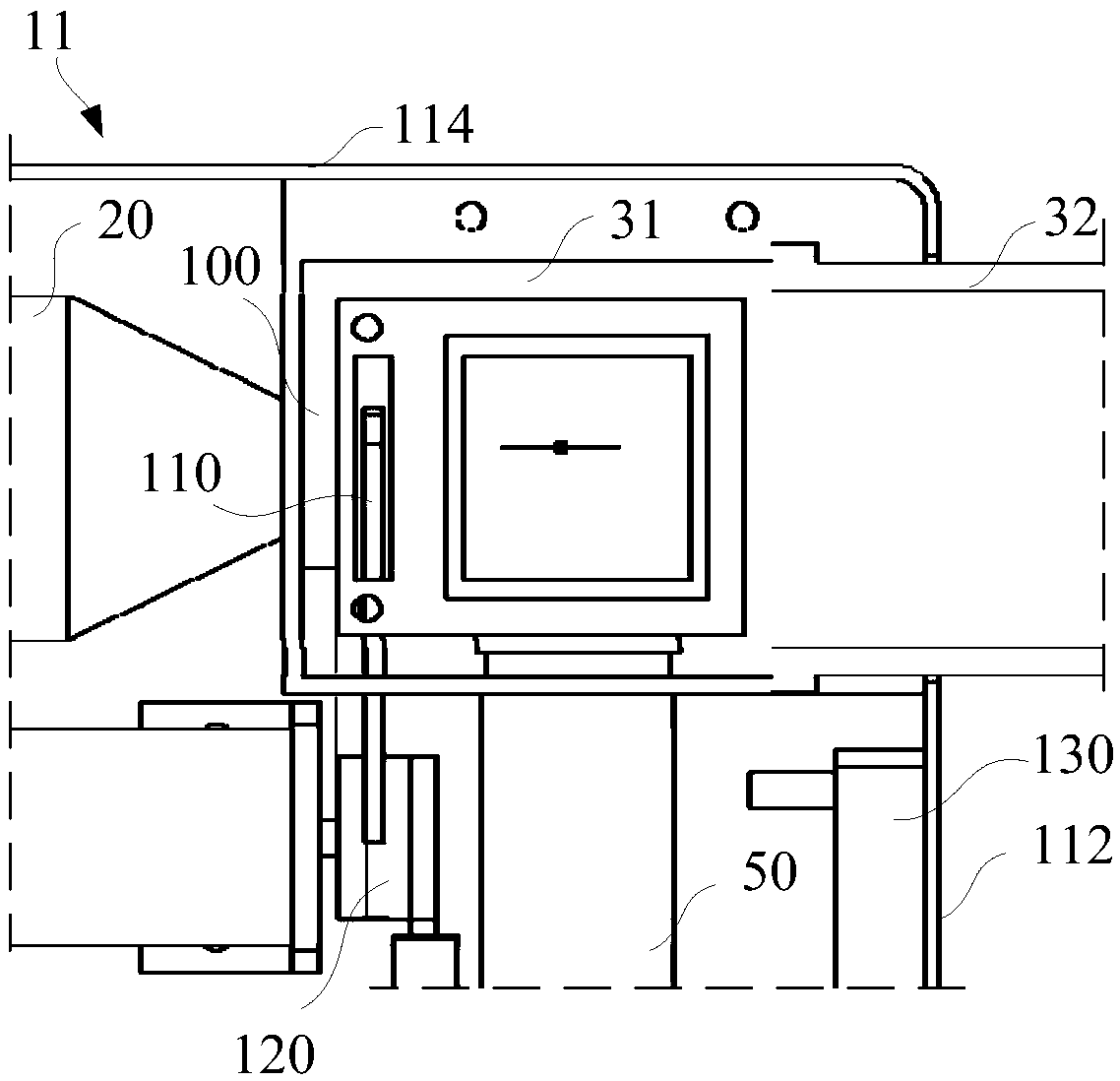
[0021] Such as figure 1 and figure 2 As shown, an XRF detector in an embodiment includes a chassis 10 , a light source module 20 , a sample chamber 30 , a detector 50 , a control and processing circuit 60 , a tablet computer 70 , a power module 80 and a power switch 90 . The light source module 20 , the sample chamber 30 , the detector 50 , the control and processing circuit 60 , and the power module 80 are all arranged in the case 10 , and the tablet computer 70 and the power switch 90 are all arranged on the outer surface of the case 10 . The light source module 20 and the detector 50 are respectively connected to the sample chamber 30, the detector 50 and the tablet computer 70 are connected to the control and processing circuit 60, and the power module 80 is connected to the power switch 90 to provide electric energy for the XRF detector. Wherein, the light source module 20 is used to emit X-rays to excite the characteristic X-ray fluorescence of the sample in the sample...


PUM


Abstract

The invention relates to an XRF detector. The XRF detector comprises a case, a light source module, a sample chamber, a detector, a control and processing circuit and a tablet computer, wherein the light source module, the sample chamber, the detector and the control and processing circuit are arranged inside the case respectively; the tablet computer is arranged outside the case; the light sourcemodule and the detector are connected with the sample chamber; the detector and the tablet computer are connected with the control and processing circuit respectively; the light source module is usedfor emitting X ray so as to stimulate the characteristic X ray fluorescence of a sample; the detector is used for receiving the characteristic X ray fluorescence and processing analytical data; the control and processing circuit is used for transmitting the analytical data into the tablet computer; and a shutter contactor for starting the light source module is arranged on the sample chamber. According to the XRF detector, the components such as the light source module, the sample chamber and the detector are arranged inside the case respectively, the XRF detector is compact in structure, small in volume and light in weight, and the component contents of heavy metal elements in soil on site are detected and analyzed in real time in virtue of the XRF detector by detection staff.

Description

technical field [0001] The invention relates to an analysis instrument for detecting and measuring elemental components of materials, in particular to an XRF detector. Background technique [0002] In recent years, due to the rapid development of industry, solid waste has been continuously piled on the soil surface, harmful wastewater has continued to seep into the soil, and harmful gases and floating dust in the atmosphere have also continued to fall into the soil with rain, resulting in serious soil heavy metal pollution. Soil heavy metal pollution directly affects the structure and function of soil ecosystem, and will finally pose a threat to ecological security and people's health. Therefore, if the land is to be developed and utilized, the heavy metal elements in the soil must be detected and analyzed first. [0003] In the prior art, X-ray fluorescence (XRF) detection equipment is often used to detect and analyze soil heavy metal elements. However, the desktop X-ray ...

Claims


Application Information

Patent Timeline
IPC IPC(8): G01N23/223
CPCG01N23/223G01N2223/076G01N2223/616
Inventor 范首东朱焱
Owner 和辰(深圳)科技有限公司
Learn More