Simulation analysis method of rotational speed compensation system for centrifugal regulator

A technology of compensation system and simulation analysis, applied in design optimization/simulation, instruments, special data processing applications, etc., can solve problems such as many factors in the normal operation of the system, performance deviation of the speed compensation system, unfavorable repairs, etc., to facilitate troubleshooting And find the point of failure, improve economic benefits, and verify the effect of reliability

Inactive Publication Date: 2019-01-18
芜湖天航装备技术有限公司
View PDF0 Cites 0 Cited by
  • Summary
  • Abstract
  • Description
  • Claims
  • Application Information

AI Technical Summary

Problems solved by technology

After the constant speed transmission device works for a long time, the movement of the parts will cause wear, fatigue, deformation and other phenomena, which will cause the performance deviation of the speed compensation system. The structure of the h

Method used


Image

  • Simulation analysis method of rotational speed compensation system for centrifugal regulator
  • Simulation analysis method of rotational speed compensation system for centrifugal regulator
  • Simulation analysis method of rotational speed compensation system for centrifugal regulator

Examples


Example Embodiment

[0024] In order to make the technical means, creative features, objectives and effects of the present invention easy to understand, the present invention will be further explained below.

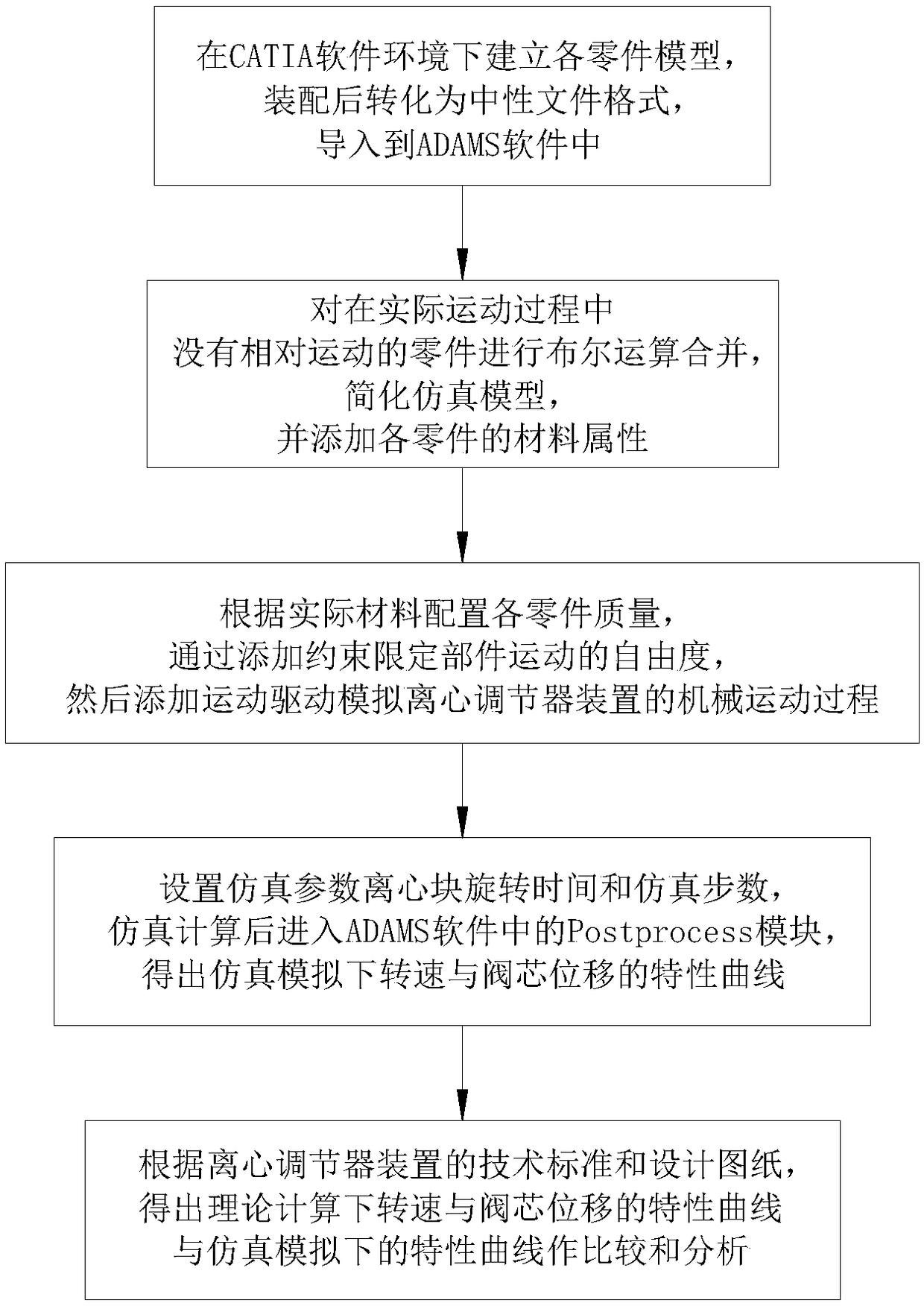
[0025] Such as Figure 1 to Figure 4 As shown, the simulation analysis method of the speed compensation system of the centrifugal regulator device includes the following steps:

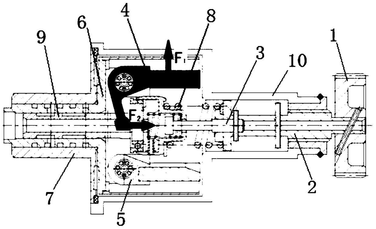
[0026] Step 1: First, use CATIA software to establish a three-dimensional model of each part of the centrifugal regulator device according to the two-dimensional drawing. The model of the main components includes turbine 1, regulating block 2, regulating rod 3, speed regulating spring 8, centrifugal block 4, centrifugal Block seat 5, rotary valve sleeve 6, valve core 9, valve sleeve 7, after creating the correct three-dimensional model, you need to save it as a neutral file in "x_t" format, and then import it into the ADAMS software;

[0027] Step 2: After completing the ADAMS software import, rename each part, and perform...


PUM


Abstract

The invention relates to a simulation analysis method for a rotational speed compensation system of a centrifugal regulator device, which comprises the following steps: firstly, establishing a model of each part under a CATIA software environment, converting the model into a neutral file format after assembly, and importing the model into an ADAMS software; 2, carrying out Boolean operation on theparts without relative motion in the actual movement process, simplifying the simulation model, and adding the material attributes of each part; 3, setting that mass of each part according to the actual material, limiting the degree of freedom of the movement of the parts by adding constraint, and driving the mechanical movement process of the simulation centrifugal regulator device by adding motion; 4, setting simulation parameters, entering Postprocess module in ADAMS software after simulation calculation, and obtaining characteristic curve of rotational speed and valve spool displacement under simulation;5, obtaining the characteristic curves of rotational speed and spool displacement under theoretical calculation and comparing the same with the characteristic curves under simulation.The centrifugal regulator device is simulated and modeled, the invention is favorable for guiding the repair of the constant speed transmission device.

Description

technical field [0001] The invention relates to the technical field of a simulation method for a centrifugal regulator, in particular to a simulation analysis method for a rotational speed compensation system of a centrifugal regulator device. Background technique [0002] The constant speed transmission is an important component in the aircraft power system, which is used to convert the changing speed of the engine output into a constant speed. After the constant speed transmission device works for a long time, the movement of the parts will cause wear, fatigue, deformation and other phenomena, which will cause the performance deviation of the speed compensation system. The structure of the high-speed transmission device is complex, and there are many factors that affect the normal operation of the system. It is difficult to troubleshoot the constant-speed transmission device and find the cause of the fault, which is not conducive to repair. [0003] As the main component ...

Claims


Application Information

Patent Timeline
IPC IPC(8): G06F17/50
CPCG06F30/20G06F2119/06
Inventor 蔡沛军钱福平王悦罗雁彭杰
Owner 芜湖天航装备技术有限公司
Why Eureka
Try Eureka