Gyrotron collector collection profile design method and gyrotron collector and gyrotron

A design method and collector technology, applied in the microwave field, can solve the problems of limited collector power capacity, device vacuum degree drop, and high collector temperature, so as to improve the collection area and collection uniformity, improve the design speed, and accurately predict Effect

Active Publication Date: 2019-01-18
UNIV OF ELECTRONICS SCI & TECH OF CHINA
View PDF6 Cites 2 Cited by
  • Summary
  • Abstract
  • Description
  • Claims
  • Application Information

AI Technical Summary

Benefits of technology

This patented technology helps improve the performance of a device called a gyroscope tubular collector by create a more accurate simulation of how charged particles move through space without colliding with other objects or being affected during flight time. It also allows for faster analysis times while maintaining accuracy over all possible trajectory paths within the same range.

Problems solved by technology

This technical problem addressed by this patented describes how to improve the efficiency at generating high pulsed powers from a large waveguide (a type called GW) used in electrical devices such as radar systems or microwave ovens without causing damage due to overheating caused by heat generated during use.

Method used


Image

  • Gyrotron collector collection profile design method and gyrotron collector and gyrotron
  • Gyrotron collector collection profile design method and gyrotron collector and gyrotron
  • Gyrotron collector collection profile design method and gyrotron collector and gyrotron

Examples


Embodiment Construction

[0052]The specific embodiments of the present invention will be described in detail below in conjunction with the accompanying drawings, so that those skilled in the art can understand the present invention. However, it should be clear that the embodiments described below are only some, not all, embodiments of the present invention. Without departing from the spirit and scope of the present invention defined and determined by the appended claims, all other embodiments obtained by persons of ordinary skill in the art without any creative effort shall fall within the protection scope of the present invention.

[0053] A method for designing a collection profile of a gyrotron collector, specifically as follows:

[0054] 1. According to the total dissipation power P collected by the collector of the gyrotron loss and the collection capacity per unit area P s , to calculate the collection area S:

[0055]

[0056] 2. According to the collection area S, calculate the optimal a...


PUM


Abstract

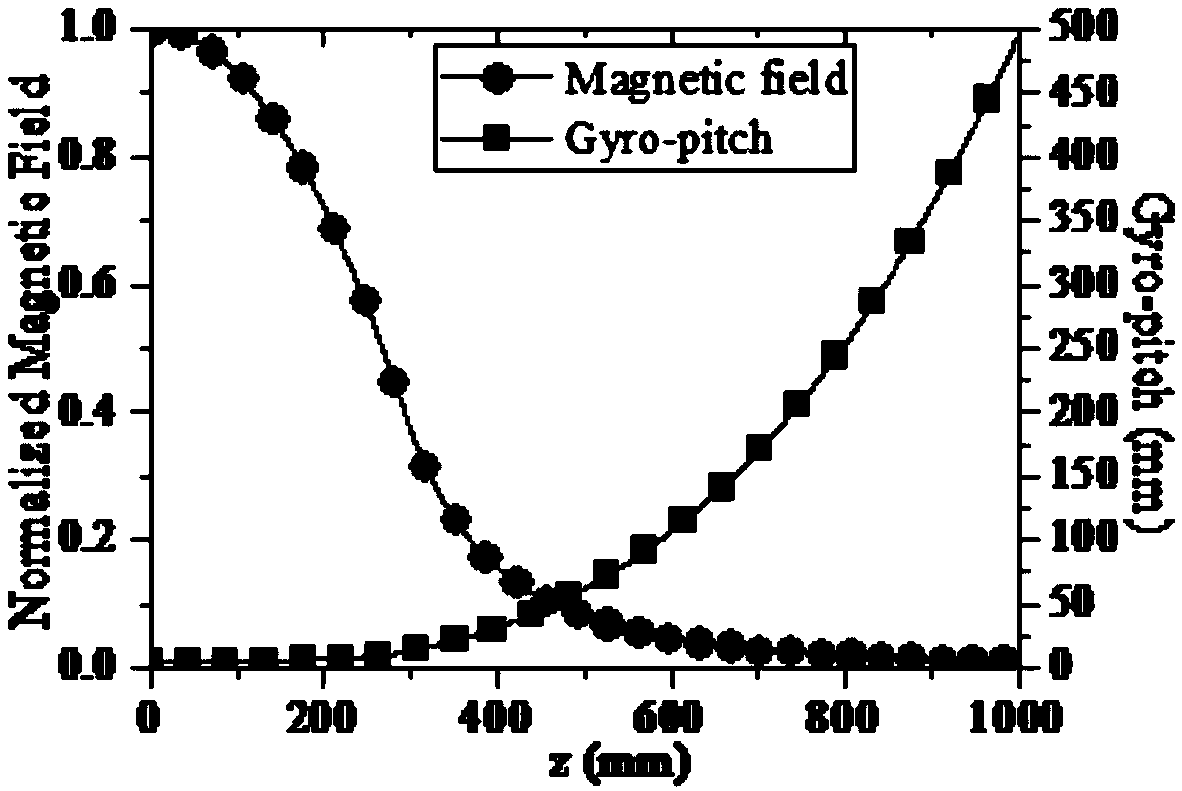
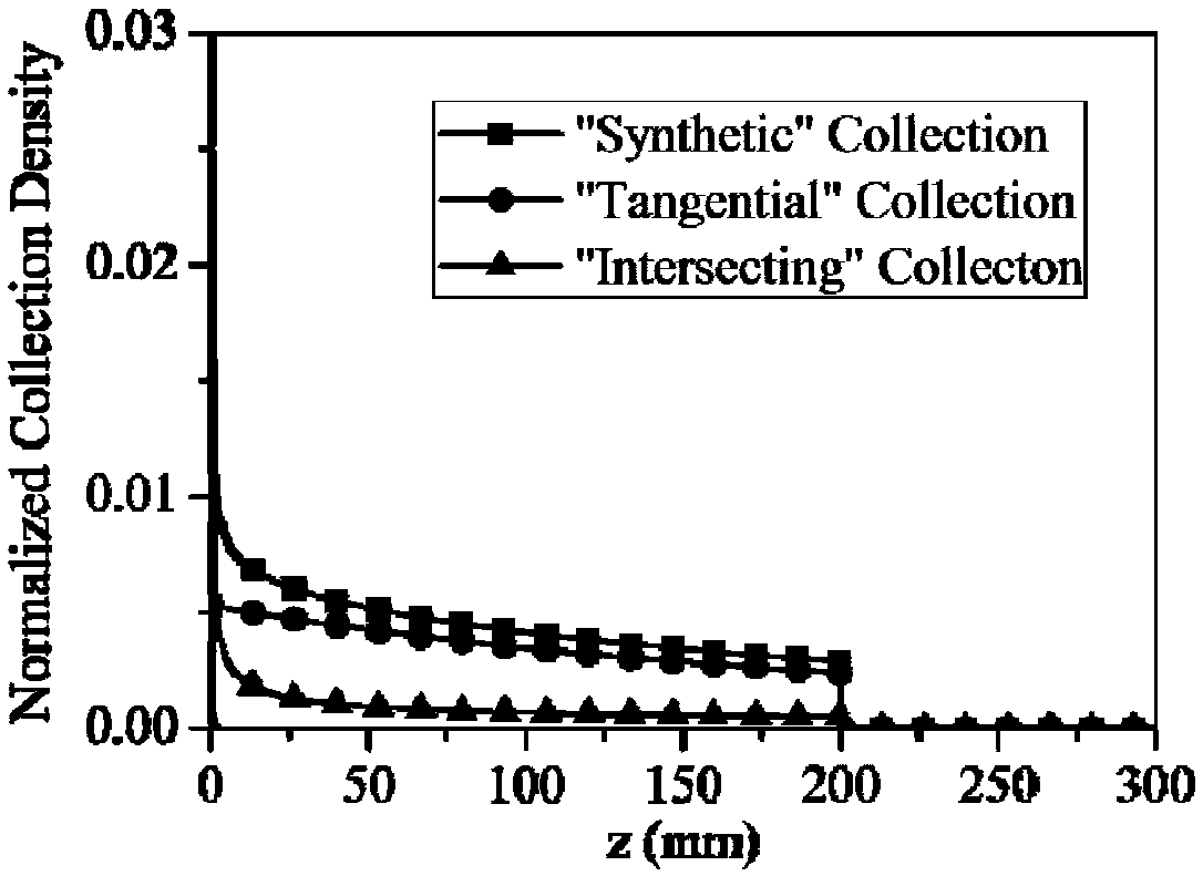
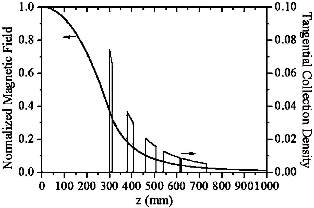
A gyrotron collector collection profile design method and gyrotron collector and gyrotron are disclosed. An electron trajectory inverse tracking method is proposed. The collecting density function isderived from the collecting pole collecting profile equation and electron beam moving trajectory equation, and the relationship between collecting density function, collecting profile and magnetic field distribution is established. By discussing the relationship between collection uniformity and applied magnetic field, collection area, the collection profile and magnetic field distribution neededin homogeneous collection are deduced. The trajectory of electron motion can be obtained from the magnetic field distribution, and the corresponding curved surface collector structure can be designedby using the collector profile. Based on this, the maximization of the collection area and the uniformity of the collection can be realized under the premise of guaranteeing a certain power capacity.The gyrotron collector includes a hollow heat dissipation structure having an internal profile designed in accordance with the above method. The gyrotron includes the gyrotron collector described above.

Description


Claims


Application Information

Patent Timeline
Owner UNIV OF ELECTRONICS SCI & TECH OF CHINA
Why Eureka
Try Eureka