A control method of a motor driving system

A technology of a motor drive system and a control method, which is applied in the field of motors and can solve problems such as unreliable performance, high cost, and poor fault tolerance

Active Publication Date: 2019-01-18
WUXI SINE POWER TECH CO LTD
View PDF9 Cites 9 Cited by
  • Summary
  • Abstract
  • Description
  • Claims
  • Application Information

AI Technical Summary

Problems solved by technology

[0007] In view of this, the object of the present invention is to provide a control method for a motor drive system, which proposes the structural design of multiple winding units respectively arranged on different stator teeth, which effectively s

Method used


Image

  • A control method of a motor driving system
  • A control method of a motor driving system
  • A control method of a motor driving system

Examples


Embodiment 1

[0102] This embodiment 1 proposes an electric vehicle, including an electric vehicle installation frame and a motor drive system that are installed and connected as one. Specifically, in this embodiment, the electric vehicle is an electric motorcycle, and its input power ranges from 400W to 10KW. Preferably, the input power range is 1KW-10KW, and within the range of medium and high-power electric vehicles, the technical effect of the present invention will be even greater;

[0103] See Figure 14 As shown, the motor drive system in this embodiment includes a three-phase AC motor and a controller group for controlling the three-phase AC motor. Specifically, preferably, in Embodiment 1, the three-phase AC motor is a permanent magnet motor, More specifically, in this embodiment, a permanent magnet synchronous hub motor is used;

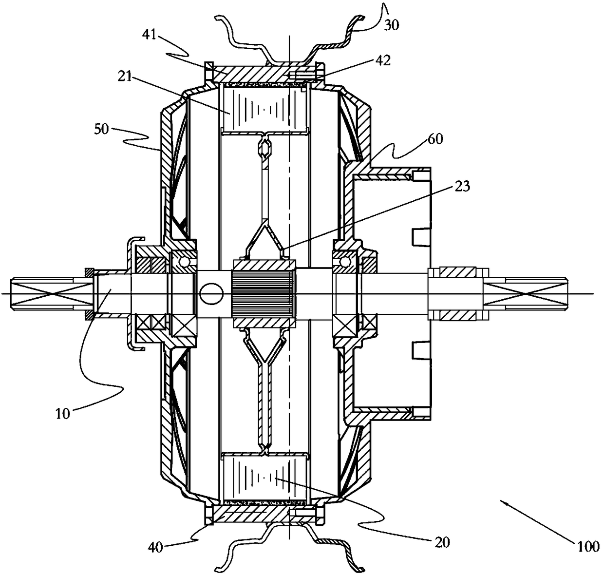
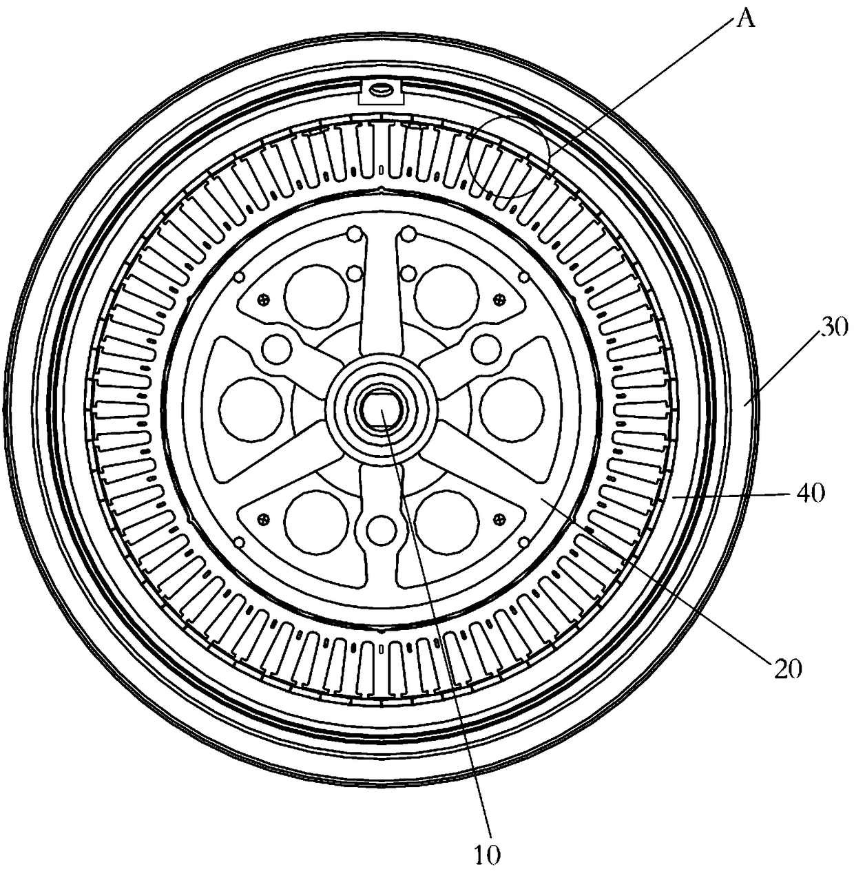
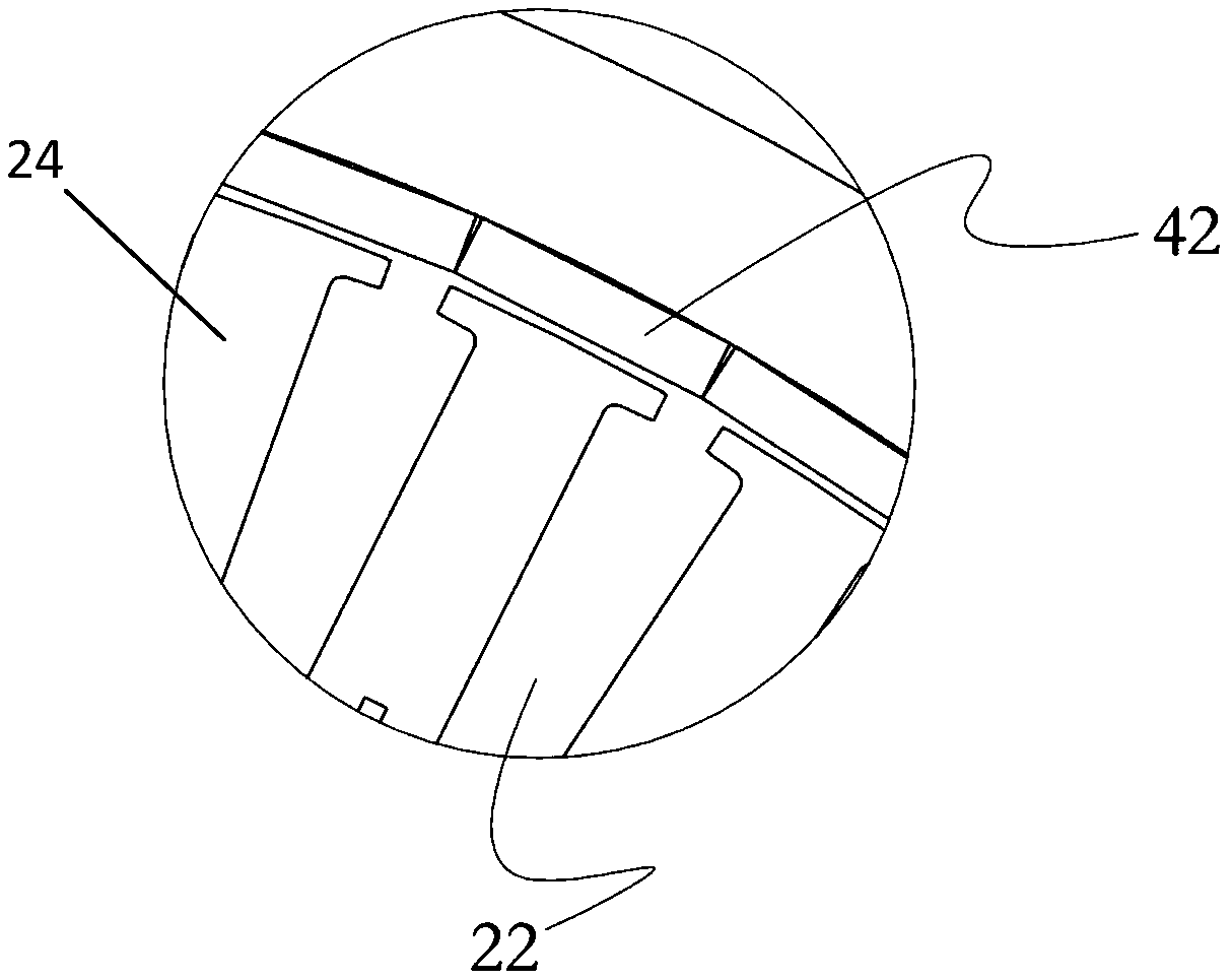
[0104] See figure 1 The shown permanent magnet synchronous hub motor 100 includes a stator 20 integrally connected with the motor shaft 10, a permanen...

Embodiment 2

[0132] Embodiment 2: The remaining technical solutions of this embodiment 2 are the same as those of embodiment 1, the difference being that: in this embodiment 2, the electric vehicle is an electric two-wheeled vehicle; wherein, the output power range of the permanent magnet synchronous hub motor is 180W-1.5 KW, the speed range of normal operation is 500-1000 rpm, and the input current range of each winding unit is 1-100A; the specific size specification, number of stator slots and number of permanent magnet steel pieces of permanent magnet synchronous hub motor can be determined according to The above-mentioned functional parameters of the permanent magnet synchronous hub motor required by this embodiment 2 are used to make a specific selection, specifically, the permanent magnet synchronous hub motor for electric two-wheeled vehicles of the prior art can be selected;

[0133]Although this embodiment 2 can also reduce the capacity of the motor driver, since the input power of...

Embodiment 3

[0134] Embodiment 3: the remaining technical solutions of this embodiment 3 are the same as those of embodiment 1, the difference being that: in this embodiment 3, the electric vehicle is an electric tricycle; wherein, the output power range of the permanent magnet synchronous hub motor is 250W-15KW, More preferably, the output power range is 1KW-15KW, the speed range during normal operation is 500-2000 revolutions per minute, and the input current range of each winding unit is 10-200A; specifically preferably, in this embodiment, the permanent The output power of the magnetic synchronous hub motor 100 is 10KW, the speed range during normal operation is 800-1200 revolutions per minute, and the input current of each winding unit is 30A, wherein, the specific dimensions and specifications of the permanent magnet synchronous hub motor of the present embodiment 3 Specific selections can be made according to the above-mentioned functional parameters of the permanent magnet synchrono...


PUM

PropertyMeasurementUnit
Outer diameteraaaaaaaaaa

Abstract

The invention discloses a control method of a motor driving system. The motor driving system comprises a three-phase alternating current motor and a controller group for controlling the three-phase alternating current motor. The stator of the three-phase alternating current motor adopts two or more winding units; The controller group includes motor driver units electrically connected to each of the winding units, and the motor driver units are used for controlling the operation of the winding units corresponding to the motor driver units. Wherein the controller group performs centralized coordinated management control on the operation states of each of the motor driver units, wherein, after the centralized coordinated management control performs communication aggregation on the operation states of each motor driver unit, the controller group determines control instructions according to the operation state aggregation information and executes the control instructions to meet the controlrequirements of the motor driving system.

Description

technical field [0001] The invention belongs to the field of motors, and in particular relates to a control method for a motor drive system. Background technique [0002] Just as the Chinese invention patent application with the publication number CN102497055A records in its background technology: traditional motors, especially medium and high-power motors, as an important component of the motor drive system, generally use a single large-capacity power driver to directly drive the motor in practical applications. Or use multiple small-capacity drivers to drive the motor in parallel, which is to combine multiple small-capacity drivers into a large-capacity driver; the driver can be directly connected to the motor, and the structure is simple, but because the traditional motor is a single set of winding structure, the large-capacity driver and In the complex application environment of traditional motors, the reliability of both of them is reduced to varying degrees. If there i...

Claims


Application Information

Patent Timeline
IPC IPC(8): H02K1/16H02K1/14H02K3/28H02K11/33H02P25/16B60K1/00
CPCB60K1/00H02K1/14H02K1/165H02K3/28H02K11/33H02P25/16
Inventor 卜言柱胡宜豹李玉刚花为何金城刘竹园李升刘亚军程兴张力胡金龙王伟王庆周建华周维丁建国庾杰
Owner WUXI SINE POWER TECH CO LTD
Why Eureka
Try Eureka