A motor based on rotor position recognition
A rotor position and rotating sleeve technology, which is applied in the direction of electromechanical devices, electrical components, mechanical equipment, etc., can solve the problem of difficult identification of the rotor position, and achieve the effects of avoiding over-rotation, protecting equipment, and improving accuracy
- Summary
- Abstract
- Description
- Claims
- Application Information
AI Technical Summary
Problems solved by technology
Method used
Image
Examples
Embodiment 1
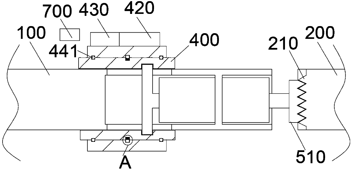
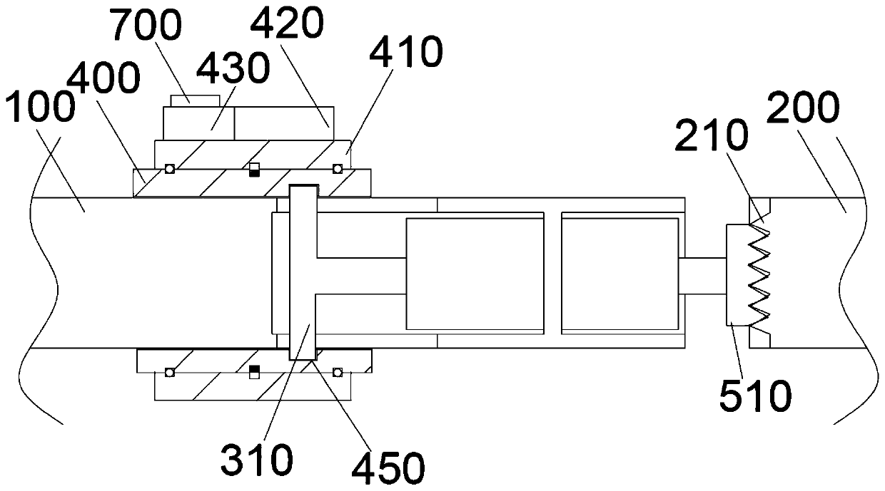
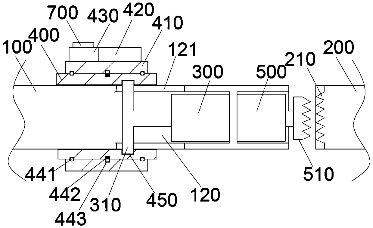
[0037] Such as Figure 1-6 As shown, the present invention provides a motor based on rotor position recognition. The coupling 400 is axially slidably sleeved on the output shaft 100 of the motor. Specifically, the inner diameter of the coupling 400 is the same as that of the output shaft 100 of the motor. The outer diameters of the couplings 400 and 400 are axially provided with a number of second slots 402 on the outer circumference of the motor output shaft 100. The bar is clamped in the second groove 402 so that the coupling 400 moves axially on the motor output shaft 100 , and the second groove 402 provides a guide for the axial movement of the coupling 400 .
[0038] An accommodating cavity 120 is provided in the end of the motor output shaft 100, and the bodies of the first telescopic mechanism 300 and the second telescopic mechanism 500 are fixedly installed in the accommodating cavity 120, so that the first telescopic mechanism 300 and the second telescoping mechanism...
Embodiment 2
[0066] Such as Figure 7-9 As shown, on the basis of Embodiment 1, this embodiment additionally adds an angular displacement sensor that detects the relative rotation angle of the rotating sleeve 410 and the coupling 400, and indirectly judges the position of the load, so that the load can be started directly without resetting. .
[0067] Specifically, at least a second concave cavity 413 is provided on the inner wall of the rotating sleeve 410, and a reading head 412 is fixedly installed in the second concave cavity 413, and the reading head 412 rotates synchronously with the rotating sleeve 410. 412 is connected with the control unit; the outer wall of the coupling 400 is provided with a fifth groove 404 corresponding to the second cavity 413 in the circumferential direction, and an angular displacement is fixedly installed in the fifth groove 404 The ball scale 403, the position of the angular displacement ball scale 403 is fixed with the coupling 400, and the reading head...
PUM
 Abstract
Description
Claims
Application Information
 - R&D
- Intellectual Property
- Life Sciences
- Materials
- Tech Scout
- Unparalleled Data Quality
- Higher Quality Content
- 60% Fewer Hallucinations
Browse by: Latest US Patents, China's latest patents, Technical Efficacy Thesaurus, Application Domain, Technology Topic, Popular Technical Reports.
© 2025 PatSnap. All rights reserved.Legal|Privacy policy|Modern Slavery Act Transparency Statement|Sitemap|About US| Contact US: help@patsnap.com


