
An energy release device for a new energy motor is disclosed

A technology of energy discharge and motor testing, which is applied in the direction of motor generator testing, output power conversion devices, electrical components, etc., can solve problems such as burning out controllers, burning out motors and controllers, and potential safety hazards, and achieves The effect of protecting from being damaged

Pending Publication Date: 2019-01-18
国充充电科技江苏股份有限公司
View PDF0 Cites 0 Cited by
  • Summary
  • Abstract
  • Description
  • Claims
  • Application Information

AI Technical Summary

Problems solved by technology

[0002] At present, the laboratory and production tests of mainstream new energy motors use the power battery simulation power supply, which greatly improves the test efficiency, but it also has its own shortcomings of burning out the motor and controller in emergencies. The nature of the power battery simulation power supply is a bidirectional power supply, which can not only provide the energy required for the operation of the test motor or motor controller, but also feed back the electromotive force during the test process to the grid
This kind of power battery simulation power supply has no problem in the test under normal conditions, but once the power supply is suddenly cut off (tripped), protected or damaged, it will cause the reverse electromotive force of the motor to have no discharge circuit, resulting in a sharp rise in the DC bus voltage until it burns out. Bad controller, there are potential safety hazards, and cause a lot of economic losses

Method used


Image

  • An energy release device for a new energy motor is disclosed

Examples


Embodiment Construction

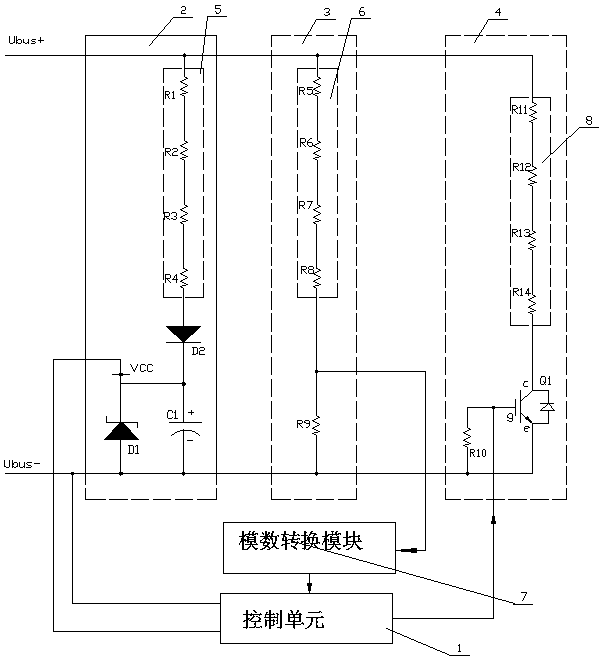
[0014] Such as figure 1 As shown, the present invention includes a control unit 1, a power supply unit 2 connected in parallel at both ends of the DC bus of the motor, a voltage sampling unit 3, and an energy discharge power unit 4. The control unit 1 described in this embodiment adopts a single-chip microcomputer.

[0015] The power supply unit 1 includes a current-limiting resistor 5, a voltage stabilizing diode D1, a diode D2, and a supercapacitor C1. The current-limiting resistor 5, diode D2, and supercapacitor C1 are connected in series in sequence. It will affect the main power part, which can be composed of one or more resistors connected in series. The current limiting resistor 5 of this embodiment is composed of resistors R1, R2, R3, and R4 connected in series, and the voltage regulator diode D1 is connected to the supercapacitor C1 in parallel. Both ends of the control unit 1 are connected to the power supply terminal of the control unit 1, and as the power supply of...


PUM


Abstract

An energy release device for a new energy motor relates to an energy release circuit, and comprises a control unit and a power supply unit, a voltage sampling unit and an energy discharge power unit which are connected to two ends of a motor direct current bus in parallel, wherein the output end of the power supply unit is connected with the power supply end of the control unit, the voltage sampling unit is connected with the input end of the control unit, and the energy discharge power unit is connected with the output end of the control unit. The invention can be directly installed at the output end of the power battery analog power supply, and can also be directly used as a separate module, so as to provide an effective energy release loop when the power battery analog power supply is suddenly cut off or damaged, and protect the motor controller from being damaged.

Description

technical field [0001] The invention relates to an energy discharge circuit, in particular to an energy discharge device for testing new energy motors. Background technique [0002] At present, the laboratory and production tests of mainstream new energy motors use the power battery simulation power supply, which greatly improves the test efficiency, but it also has its own shortcomings of burning out the motor and controller in emergencies. The essence of the power battery simulation power supply is a bidirectional power supply, which can not only provide the energy required for the operation of the test motor or motor controller, but also feed the feedback electromotive force during the test process back to the grid. This kind of power battery simulation power supply has no problem in the test under normal conditions, but once the power supply is suddenly cut off (tripped), protected or damaged, it will cause the reverse electromotive force of the motor to have no discharg...

Claims


Application Information

Patent Timeline
Patent Type & Authority Applications(China)
IPC IPC(8): H02M1/32G01R31/34
CPCH02M1/32G01R31/34H02M1/322
Inventor 宋文弟潘小刚孙前双严松
Owner 国充充电科技江苏股份有限公司
Learn More