Voltage sag treatment device and implementation method

A technology of voltage sag and voltage, applied in the field of electric power, can solve the problems of reducing the reliability of load power supply, reducing the ability of load voltage compensation, and poor reliability, etc., to achieve the effects of reducing hidden failures, increasing service life, and improving reliability

Pending Publication Date: 2022-04-26
GUANGZHOU POWER SUPPLY BUREAU GUANGDONG POWER GRID CO LTD
View PDF0 Cites 0 Cited by
  • Summary
  • Abstract
  • Description
  • Claims
  • Application Information

AI Technical Summary

Problems solved by technology

In order to save costs, the energy storage modules used in the voltage sag control device use fewer energy storage modules, so that the DC voltage of the energy storage modules cannot reach the DC bus voltage required by the inverter. A bidirectional DC / DC converter is added between the energy modules to convert the voltage of the lower energy storage module into the DC bus voltage required by the inverter. However, the bidirectional DC / DC converter in the voltage sag control device and Bidirectional rectifier inverters are all power electronic devices. The switching devices of power electronic devices are prone to failure after long-term operation, and the dynamic voltage compensation device is located in the distribution network. The electromagnetic environment of the device is poor, and the power electronic device It is sensitive to electromagnetic interference, and the power electronic device itself will act as a source of electromagnetic interference to interfere with other power electronic devices. In severe cases, the power electronic device may not work. Compared with the energy storage module and power transformer, the power electronic device In terms of high failure rate and poor reliability, the reliability of the voltage sag control device is low
[0009] Since the current off-line dynamic voltage restorers all have anti-parallel thyristors connected in series to the power grid circuit to prevent energy from being injected into the grid side when the dynamic voltage restorer is working, reducing the ability to compensate the load voltage, but when the anti-parallel thyristors In case of failure, the power grid cannot supply power to the load normally, reducing the reliability of power supply to the load

Method used


Image

  • Voltage sag treatment device and implementation method
  • Voltage sag treatment device and implementation method
  • Voltage sag treatment device and implementation method

Examples


Embodiment 1

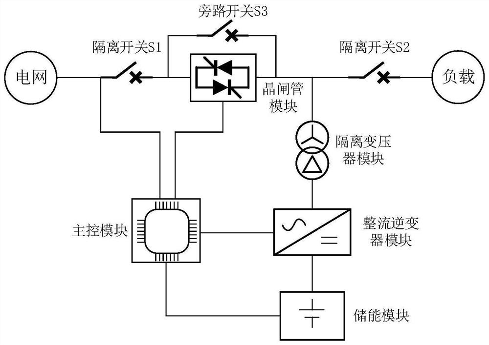
[0041] like figure 1 As shown in the figure, a voltage sag treatment device according to the present invention includes: a thyristor module, a bypass switch module, an isolation transformer module, a rectifier inverter module, an energy storage module and a main control module, the main control module being respectively connected to the thyristor module The rectifier inverter module and the energy storage module are connected, the rectifier inverter module is respectively connected with the isolation transformer module and the energy storage module, the thyristor module is connected with the isolation transformer module, and the bypass switch module is connected in parallel with both ends of the thyristor module. in:

[0042] The thyristor module is located between the grid terminal and the load terminal. When the grid voltage is normal, the module is closed, and the grid supplies power to the load normally. When a voltage sag occurs, the module disconnects the grid power supp...

Embodiment 2

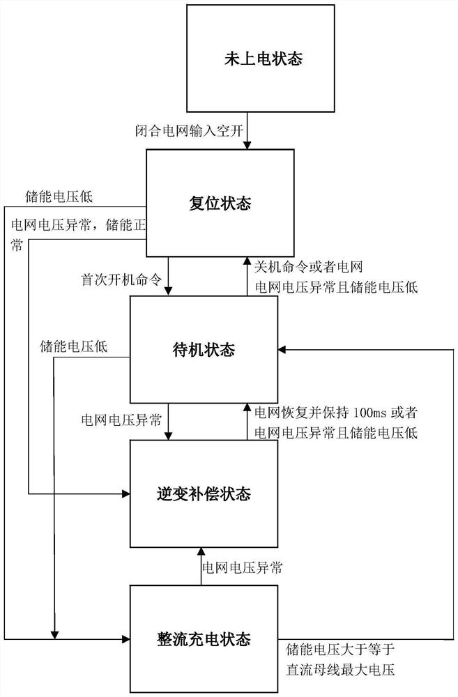
[0068] like image 3 As shown in the state logic diagram of the implementation method of the voltage sag control device, the operating state of the voltage sag control device can be divided into five states, namely the unpowered state, the reset state, the standby state, the inverter compensation state and the rectification state. ,in:

[0069] When the voltage sag control device is not powered on, the main control module does not work, the bypass switch module is disconnected, the thyristor module does not conduct, and the rectifier inverter module does not work.

[0070] When the voltage sag control device is in the reset state, the main control module works, the bypass switch module is closed, the thyristor module is turned on, and the rectifier inverter module does not work. At this time, the load is powered by the grid through the thyristor and the bypass switch, and the control circuit detects the voltage of the energy storage module and the grid voltage to determine th...


PUM


Abstract

The invention relates to the technical field of electric power, in particular to a voltage sag treatment device and an implementation method.The voltage sag treatment device comprises a thyristor module, a bypass switch module, an isolation transformer module, a rectification inverter module, an energy storage module and a main control module, and the main control module is connected with the thyristor module, the rectification inverter module and the energy storage module; the rectification inverter module is respectively connected with the isolation transformer module and the energy storage module, the thyristor module is connected with the isolation transformer module, and the bypass switch module is connected with two ends of the thyristor module in parallel; the isolation transformer module is arranged between the load and the rectification inverter module, a primary winding of the isolation transformer module is in delta connection, a secondary winding of the isolation transformer module is in star connection, and a neutral point of a secondary star side of the isolation transformer module is connected with a neutral point of a power grid. According to the invention, the load in the power grid can be ensured not to be powered down, three-phase imbalance of load voltage is avoided, the electric energy quality of load power supply is improved, and the reliability of load power supply is improved.

Description

technical field [0001] The invention relates to the field of electric power technology, and in particular to a voltage sag treatment device and an implementation method. Background technique [0002] The power quality of the power system has always been the focus and hot issue in the industry. Usually, the main indicators to measure the power quality are voltage, frequency and waveform. The ideal grid voltage waveform should be a perfectly symmetrical sine wave. Power quality problems usually include frequency deviation, voltage deviation, voltage fluctuation and flicker, three-phase unbalance, instantaneous or transient overvoltage, waveform distortion (harmonics), voltage sag, interruption, swell, and power supply continuity. [0003] GB / T12325-2008 "Power Quality Supply Voltage Deviation" stipulates that the sum of the absolute value of the positive and negative deviations of the power supply voltage of 35kV and above does not exceed 10% of the nominal voltage; the deviat...

Claims


Application Information

Patent Timeline
Patent Type & Authority Applications(China)
IPC IPC(8): H02J3/12H02J3/00H02J3/26H02J3/28H02B1/26F04D27/00
CPCH02J3/12H02J3/001H02J3/26H02J3/28H02B1/26F04D27/004Y02E40/50
Inventor 徐硕许中莫文雄周凯马智远霍建彬代晓丰童锐刘明昊王荣富
Owner GUANGZHOU POWER SUPPLY BUREAU GUANGDONG POWER GRID CO LTD
Why Eureka
Try Eureka