Stable-switching ball screw type inerter device

A ball screw type, inertial container technology, applied in the field of inertial containers, can solve the problems of inertial container performance impact, time delay, inertial force generation, etc., and achieve the effects of weakening the time delay effect, reducing nonlinear factors, and eliminating impact.

Active Publication Date: 2019-01-22
JIANGSU UNIV
View PDF9 Cites 17 Cited by
  • Summary
  • Abstract
  • Description
  • Claims
  • Application Information

AI Technical Summary

Problems solved by technology

[0003] Chinese patent application 201410650452.4 discloses a ball screw type inerter with mechanical variable inertia coefficient and variable inertia coefficient. Chinese patent application 201510461811.6 discloses an integrated screw electromechanical inerter. The above two inerters Both involve ball screw type inerters. When the screw nut changes the direction of movement, it drives the lead screw to change the direction of rotation. The flywheel and the lead screw of the above two inerters are rigidly connected. However, during the rotation of the flywheel, inertial force is generated, and the instantaneous change of direction will cause impact on the screw and the screw nut, resulting in time lag, increasing the nonlinear factor of the inerter, and having a certain impact on the performance of the inerter

Method used


Image

  • Stable-switching ball screw type inerter device
  • Stable-switching ball screw type inerter device
  • Stable-switching ball screw type inerter device

Examples


Embodiment 1

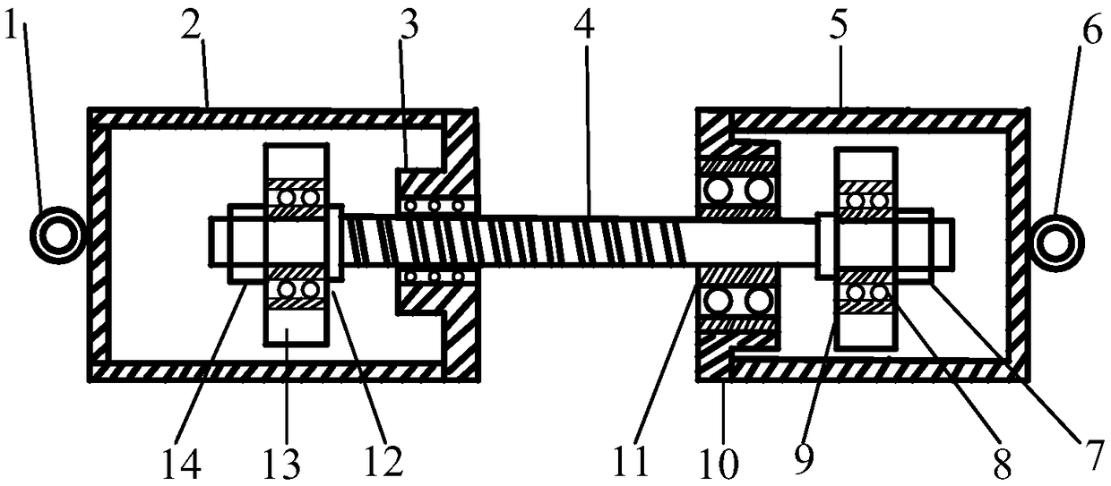
[0029] Such as figure 1 As shown, the ball screw type inerter device for steady state switching includes a left lug (1), a right lug (6), a first cylinder (2), a second cylinder (5), Lead screw nut (3), lead screw (4), bearing housing (10), bearing (11), flywheel A (13), flywheel B (9), roller type one-way clutch A (12), roller type One-way clutch B (8), pre-tightening nut A (14), pre-tightening nut B (7), the flywheel A (13) is installed on the lead screw (4) through the roller type one-way clutch A (12) At the left end, the flywheel B (9) is installed on the right end of the lead screw (4) through the roller type one-way clutch B (8), and the lead screw nut (3) is installed on the lead screw extending out of the first cylinder (2 ), and solidified together with the right end of the first cylinder (2), the bearing block (10) is solidified on the second cylinder (5), the inner ring of the bearing (11) and the lead screw (4) Consolidate together, the outer ring is installed o...

Embodiment 2

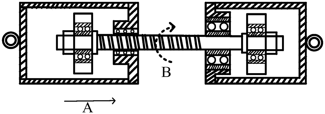
[0037] Such as Figure 5 As shown, the ball screw type inerter device for steady state switching includes a left lug (1), a right lug (6), a first cylinder (2), a second cylinder (5), Lead screw nut (3), lead screw (4), bearing housing (10), bearing (11), flywheel A (13), flywheel B (9), roller type one-way clutch A (12), roller type One-way clutch B (8), pre-tightening nut A (14), pre-tightening nut B (7), the flywheel A (13), flywheel B (9) through the roller type one-way clutch A (12), roller The column type one-way clutch B (8) is installed on the right end of the lead screw (4), and the lead screw nut (3) is installed at the position where the lead screw extends out of the first cylinder (2), and is connected with the first cylinder ( 2) the right ends are consolidated together, the bearing seat (10) is consolidated on the second cylinder (5), the inner ring of the bearing (11) is consolidated with the lead screw (4), and the outer ring is installed On the bearing seat,...


PUM


Abstract

The invention provides a stable-switching ball screw type inerter device. The stable-switching ball screw type inerter device comprises a first mounting part, a second mounting part, a first cylinderbarrel, a second cylinder barrel, a screw nut, a screw, a flywheel A, a flywheel B, a one-way clutch A and a one-way clutch B and is characterized in that the screw is mounted between the first cylinder barrel and the second cylinder barrel in a penetrating manner, one end of the screw is rotatably mounted in the first cylinder barrel, and the other end of the screw penetrates the screw nut fixedly mounted on the second cylinder barrel and is coordinated with the screw; the first mounting part is mounted at the left end of the first cylinder barrel, and the second mounting part is fixedly mounted at the right end of the second cylinder barrel; when the motion direction of the nut instantly changes, only one of the two flywheels synchronously rotates along with the screw, flywheel impact, caused by rotation direction change, on the screw during switching is avoided effectively, stable switching is achieved, influence of nonlinear factors is small, and the performance of the inerter device is improved effectively.

Description

technical field [0001] The invention relates to an inerter, in particular to a ball screw type inerter with steady switching and no impact. Background technique [0002] In 2002, Professor Smith of the United Kingdom invented the mass element with two ends - the inerter. With the research on the inerter, it has been used in the fields of automobile suspension, buildings, trains, robots and so on. Through the research, it is found that the inerter is used in In the vibration isolation system, the vibration isolation performance of the system can be effectively improved. Therefore, the research and invention of the inerter has great development potential in the field of vibration transmission. [0003] Chinese patent application 201410650452.4 discloses a ball screw type inerter with mechanical variable inertia coefficient and variable inertia coefficient. Chinese patent application 201510461811.6 discloses an integrated screw electromechanical inerter. The above two inerters...

Claims


Application Information

Patent Timeline
Patent Type & Authority Applications(China)
IPC IPC(8): F16F15/10B60G13/04
CPCB60G13/04F16F15/10
Inventor 杨晓峰李洪昌刘雁玲赵文涛沈钰杰
Owner JIANGSU UNIV
Why Eureka
Try Eureka