Al technical title is built by PatSnap Al team. It summarizes the technical point description of the patent document.
A fully automatic, riveting machine technology, applied in the direction of electrical components, circuits, connections, etc., can solve the problems of wasting manpower and low work efficiency, and achieve the effects of reducing manpower, saving costs, and compact and simple structure
Pending Publication Date: 2019-01-22
南京合力电光源设备制造厂
View PDF3 Cites 0 Cited by
Summary
Abstract
Description
Claims
Application Information
AI Technical Summary
This helps you quickly interpret patents by identifying the three key elements:
Problems solved by technology
Method used
Benefits of technology
Problems solved by technology
Low work efficiency and waste of manpower
Method used
Image
Click on the blue label to locate the original text in one second.
Reading with bidirectional positioning of images and text.
Examples
Embodiment Construction
[0018] In order to make the purpose, technical solutions and advantages of the embodiments of the present invention clearer, the technical solutions in the embodiments of the present invention will be clearly and completely described below in conjunction with the drawings in the embodiments of the present invention. Obviously, the described embodiments It is a part of the embodiments of the present invention, rather than all embodiments; based on the embodiments of the present invention, all other embodiments obtained by those of ordinary skill in the art without creative work, all belong to the protection scope of the present invention .
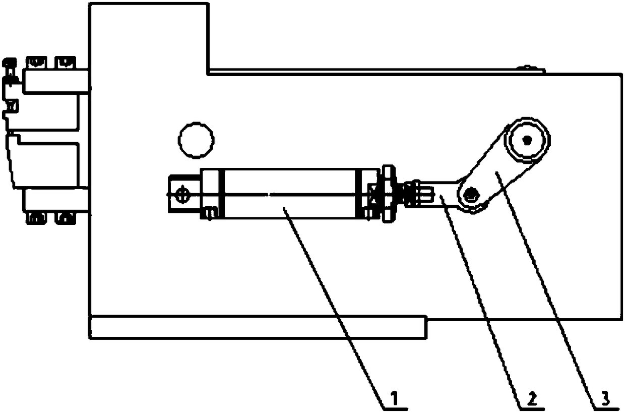
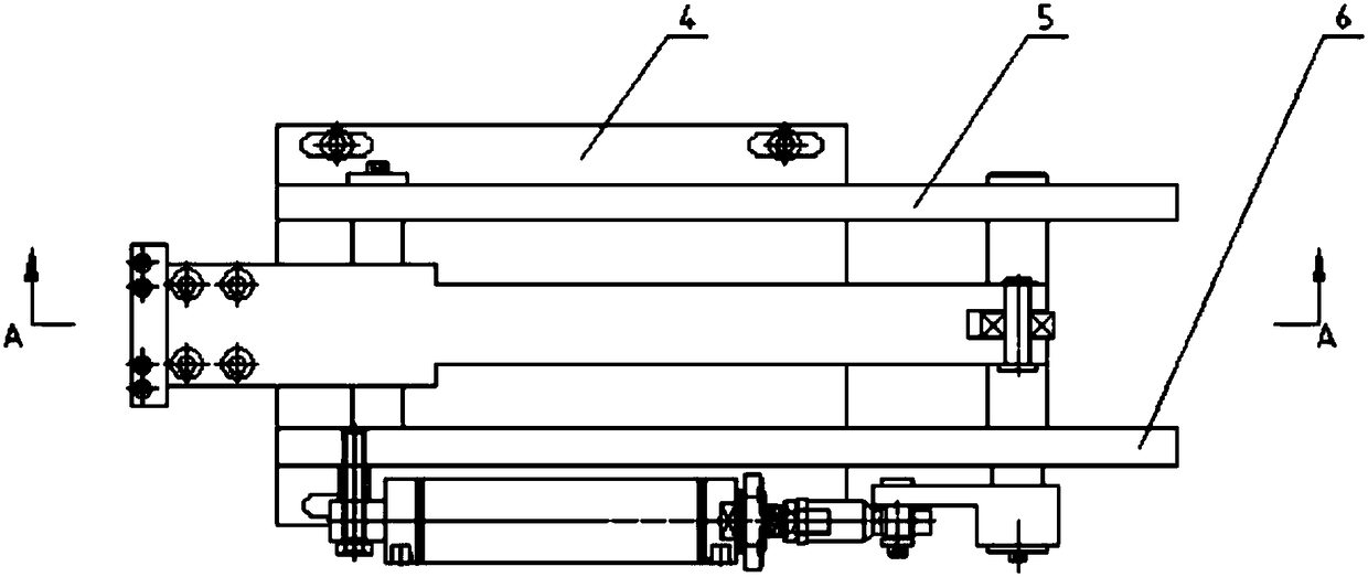
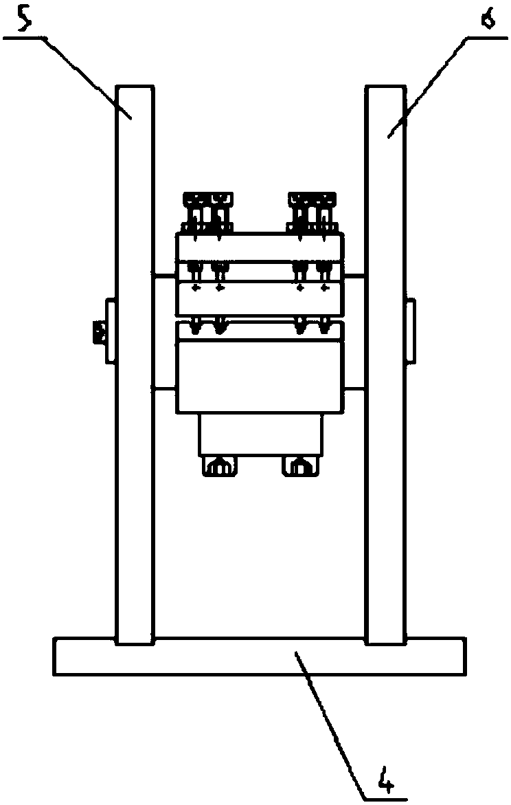
[0019] see Figure 1-6 , the present invention provides a technical solution: a fully automatic lamp pin guide wire riveting press, including a bottom plate 4, a left side plate 5 and a right side plate 6 are provided on the top of the bottom plate 4, and a side plate of the right side plate 6 is provided with Drive cylinder 1, one end of ...
PUM
Abstract
The invention provides a fully automatic lamp foot guide wire riveting machine which comprises a bottom plate, A left side plate and a right side plate are arranged on that top of the bottom plate, Adrive cylinder is arranged on one side of the right side plate, At one end of that drive cylinder, a fish-eye joint is arranged, At one end of that fish-eye joint, a driving rock arm is rotatably connected, At one end of that drive rocker arm, a drive shaft penetrate the left and right plates, a cam is arranged on the drive shaft, a rotating shaft is fixed between the left and right plates on oneside of the drive shaft, two wear-resistant sleeves are sleeved on the rotating shaft, and upper and lower connecting rods are respectively arranged on the wear-resistant sleeves. The wear-resistant sleeve and the wear-resistant pad are adopted, The utility model has the advantages of small friction, long service life, adopting a cam to drive the upper connecting rod and the lower connecting rod to rotate simultaneously, realizing two actions by one driving cylinder, compact and simple in structure, reducing driving source, riveting the lamp leg guide wire while supporting the lamp leg, and realizing automatic riveting without manual participation, reducing manpower and saving cost. The utility model has the advantages of small friction and long service life, and adopts a cam to drive theupper connecting rod and the lower connecting rod to rotate simultaneously, and realizes two actions by one driving cylinder.
Description
technical field [0001] The invention relates to the technical field of riveting presses, in particular to an automatic riveting press for guide wires of lamp pins. Background technique [0002] LED fluorescent lamps, commonly known as straight tube lamps, are a substitute for traditional fluorescent tubes, which are reflected in two aspects of energy saving and environmental protection. In the production process of LED fluorescent lamps, one end of the luminous strip needs to be welded with a guide wire, and the other end is welded with a driving circuit board. The riveting is inside the lamp pins. The current riveting machines are all semi-automatic. It is necessary to manually put the lamp pins into the riveting press and then riveting. Low work efficiency and waste of manpower. Contents of the invention [0003] The invention overcomes the deficiencies in the prior art, and the technical problem to be solved is: to provide a fully automatic lamp pin guide wire rivetin...
Claims
Application Information
Patent Timeline
Application Date:The date an application was filed.
Publication Date:The date a patent or application was officially published.
First Publication Date:The earliest publication date of a patent with the same application number.
Issue Date:Publication date of the patent grant document.
PCT Entry Date:The Entry date of PCT National Phase.
Estimated Expiry Date:The statutory expiry date of a patent right according to the Patent Law, and it is the longest term of protection that the patent right can achieve without the termination of the patent right due to other reasons(Term extension factor has been taken into account ).
Invalid Date:Actual expiry date is based on effective date or publication date of legal transaction data of invalid patent.