
Novel whipping device

A new type of mixing cup technology, which is applied in home appliances, applications, kitchen utensils, etc., can solve the problems of inability to stir, complicated structure of the whipping device, and increased energy consumption of the body, so as to achieve improved whipping effect, delicate food taste, and improved convenience effect

Pending Publication Date: 2019-01-25
唐作龙
View PDF18 Cites 1 Cited by
  • Summary
  • Abstract
  • Description
  • Claims
  • Application Information

AI Technical Summary

Problems solved by technology

[0002] Existing portable whipping devices are generally driven by electricity, and need to charge the battery in the whipping device or perform functions on the small motor by replacing the dry battery. However, the structure of the whipping device with this structure is relatively complicated and inconvenient to maintain. Problems such as high production costs, when the user finds that the power of the whipping device is insufficient when carrying it out, the whipping device can only be used as a container and cannot realize its own function, and the torque of the small motor is insufficient due to power problems. The mixing knife is easy to be stuck by the food when it is started, resulting in failure to stir, etc.
[0003] Therefore, today’s portable whipping devices are partially driven manually, with a simple structure, which minimizes the weight of the whipping device and is easy to carry when going out. Moreover, the manual mode can provide a large torque, enabling users to whip most of the food. , eliminating the need to worry about the power failure of the whipping device. However, when this part of the manual whipping device is in use, the handle can only be turned in one direction to drive the knife shaft to the direction of the blade to achieve one-way rotation, causing the hand to drive the handle It requires the whole arm to swing hard, which increases the load on the user's hand and increases the energy consumption of the body.

Method used


Image

  • Novel whipping device
  • Novel whipping device
  • Novel whipping device

Examples


no. 1 approach

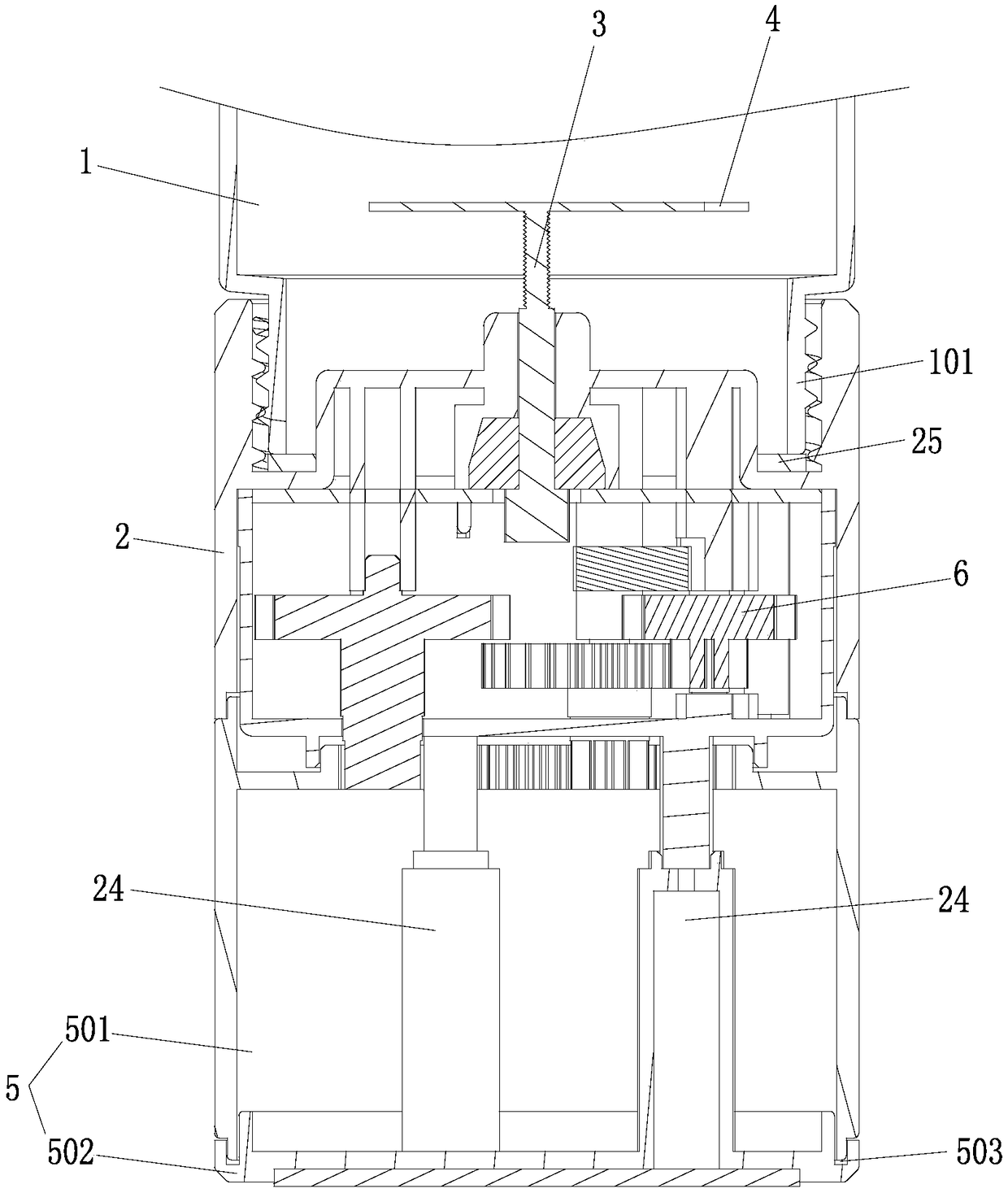
[0024] The first embodiment: as figure 1 As shown, a new type of whipping device includes a stirring cup 1, a knife seat 2 is detachably installed on the mouth 101 of the stirring cup 1, a knife shaft 3 is rotatably connected to the knife seat 2, and a stirring shaft 3 is installed on the knife shaft 3. Knife 4, the handle 5 is rotatably connected to the knife seat 2, and the gear assembly 6 connected with the knife shaft 3 is installed in the knife seat 2, and the gear assembly 6 drives the knife shaft 3 by turning the handle 5 clockwise or counterclockwise to realize one-way Rotate, the whipping device of this structure can enable the user to rotate the handle 5 repeatedly in the clockwise or counterclockwise direction, so that the mixing knife 4 can be quickly rotated in the direction of the blade for whipping, which can improve the convenience of whipping. The user only needs to use the forearm The central axis drives the hand holding the handle 5 to twist repeatedly at hi...

no. 2 approach

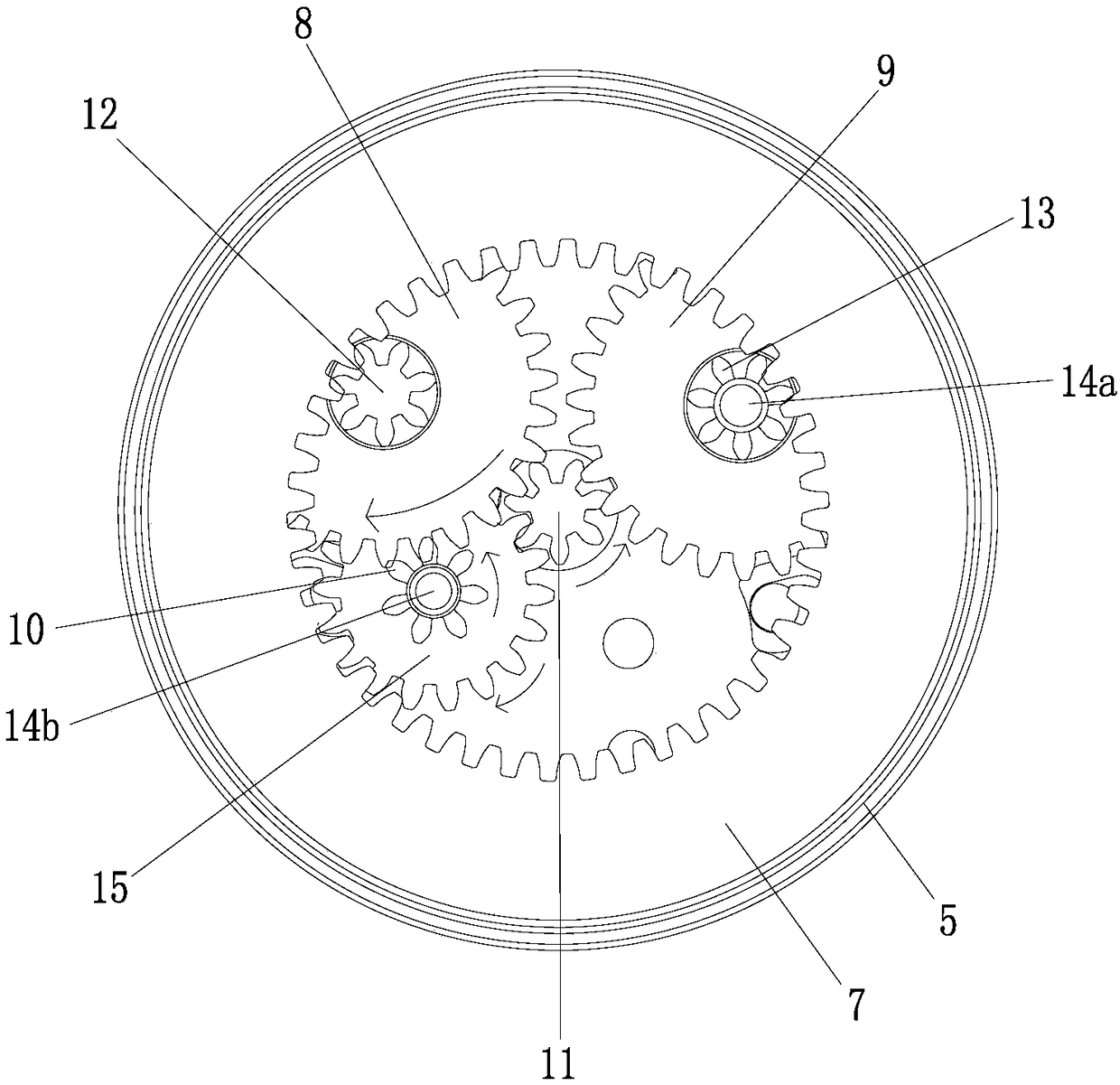
[0025] The second embodiment: as figure 2 As shown, the gear assembly 6 includes an annular internal gear 7, a forward gear 8, a reverse gear 9, a steering gear 10, and a sun gear 11. The annular internal gear 7 is fixedly installed in the handle 5, and the central axis of the forward gear 8 Connected with the first driving gear 12, the reverse gear 9 is connected with the second driving gear 13 through the rotation of the first one-way bearing 14a, the first driving gear 12 and the second driving gear 13 mesh with the annular internal gear 7 respectively, forward The gear 8 meshes with the steering gear 10, and the steering gear 10 is rotatably connected with the steering speed-up gear 15 through the second one-way bearing 14b. The steering speed-up gear 15 meshes with the central gear 11, and the central gear 11 is fixedly installed on the cutter shaft 3. The gear 9 meshes with the central gear 11. The gear assembly 6 of this embodiment simplifies the structure of the gear ...

no. 3 approach

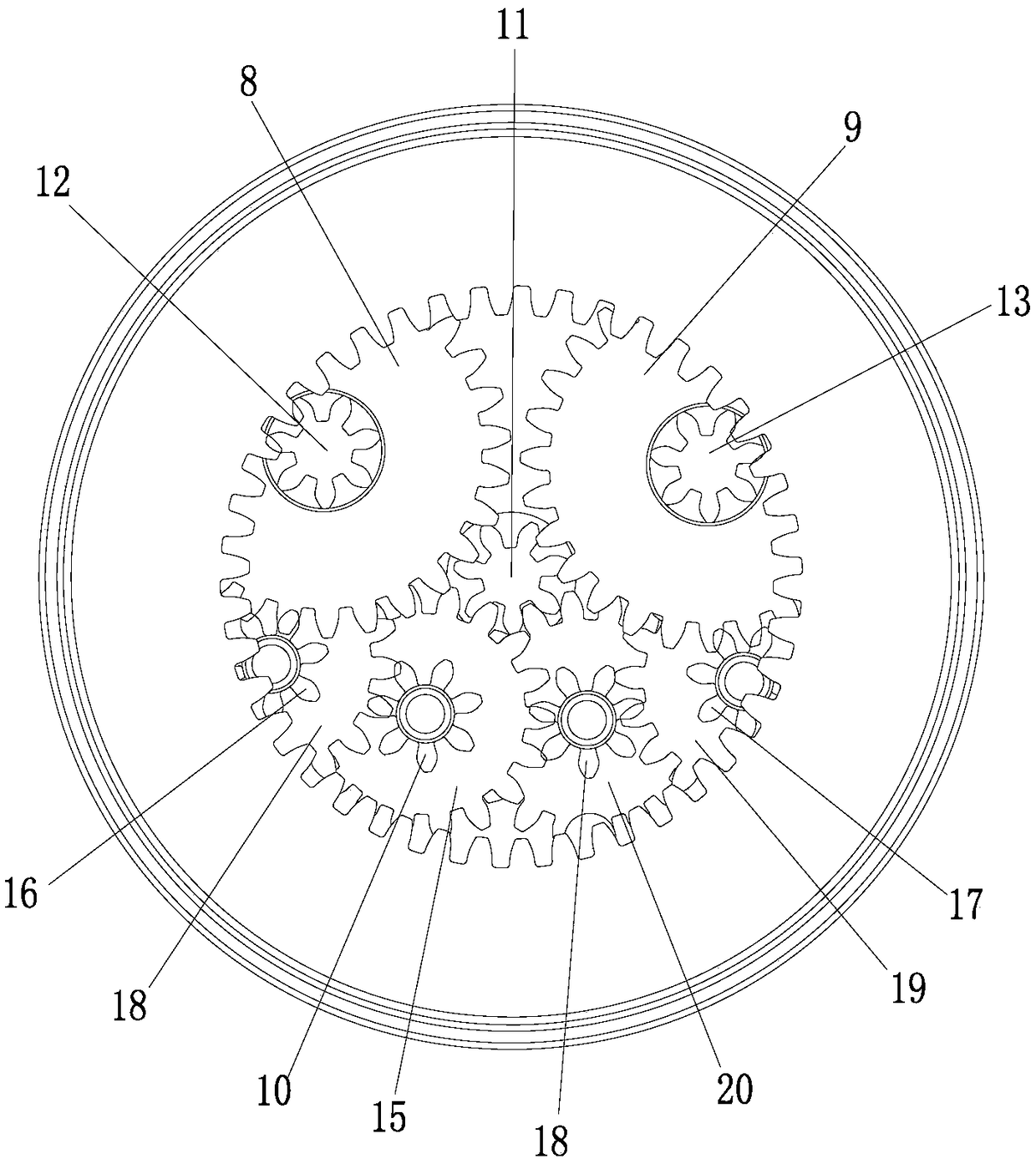
[0028] The third embodiment: as image 3As shown, the gear assembly includes an annular internal gear 7, a forward gear 8, a reverse gear 9, a steering gear 10, a first intermediate gear 16, a second intermediate gear 17, a transmission gear 18 and a sun gear 11, and the annular internal gear 7. It is fixedly installed in the handle 5. On the central axis of the forward gear 8 and the reverse gear 9, the first driving gear 12 and the second driving gear 13 are respectively connected, and the first driving gear 12 and the second driving gear 13 are connected with the annular The internal gear 7 meshes, and the first intermediate gear 16 and the second intermediate gear 17 are swingably installed in the tool holder 2. The first speed-up gear 18 and the second intermediate gear 18 are respectively connected on the central axis of the first intermediate gear 16 and the second intermediate gear 17. The speed-up gear 19, the first intermediate gear 16 and the second intermediate gea...


PUM


Abstract

A novel whipping device includes a stirring cup, a knife holder is detachably mounted on the cup mouth of the stirring cup, a knife shaft is rotatably connected with the knife holder, a knife shaft isprovided with a stirring knife, a handle is rotatably connected with that knife holder, a gear assembly coupled to the cutter shaft is mounted in the cutter holder, the gear assembly rotates the handle shaft clockwise or counterclockwise to drive the knife shaft unidirectionally, the whipping device of the structure enables the user to repeatedly rotate the handle in a clockwise or counterclockwise direction, the agitating knife is quickly rotated in the direction of the knife edge to whip, the invention can improve the convenience of whipping, the user only needs to drive the hand of the grip handle with the forearm as the center shaft to rotate the whipping knife at high speed and repeatedly, and the whipping knife can rotate at high speed with a very short rotating stroke of the handlein a short time, thereby improving the whipping effect and making the food taste more delicate.

Description

technical field [0001] The invention relates to the field of whipping devices, in particular to a novel whipping device. Background technique [0002] Existing portable whipping devices are generally driven by electricity, and need to charge the battery in the whipping device or perform functions on the small motor by replacing the dry battery. However, the structure of the whipping device with this structure is relatively complicated and inconvenient to maintain. Problems such as high production costs, when the user finds that the power of the whipping device is insufficient when carrying it out, the whipping device can only be used as a container and cannot realize its own function, and the torque of the small motor is insufficient due to power problems. The mixing knife is easy to be stuck by the food when it is started, resulting in failure to stir and so on. [0003] Therefore, today’s portable whipping devices are partially driven manually, with a simple structure, wh...

Claims


Application Information

Patent Timeline
Patent Type & Authority Applications(China)
IPC IPC(8): A47J43/046A47J43/08
CPCA47J43/046A47J43/085
Inventor 谢其海唐作龙汤平
Owner 唐作龙
Learn More