Supercharge Your Innovation With Domain-Expert AI Agents!

Punch and stamping device

A stamping device and punch technology, which is applied in the field of stamping, can solve the problems of products and punches getting hot, unable to guarantee the yield and benefit of output products, and slow speed, etc., to achieve increased stamping speed, simple structure, and reduced defect rate Effect

Pending Publication Date: 2019-01-25
东莞市骏毅机电科技有限公司
View PDF7 Cites 0 Cited by
  • Summary
  • Abstract
  • Description
  • Claims
  • Application Information

AI Technical Summary

Problems solved by technology

[0003] The purpose of the present invention is to provide a punch and a stamping device to solve the problem of heat caused by the extrusion friction of the stamping die during the working process, the product and the punch are seriously heated, and the speed is not fast, resulting in the failure to ensure the yield and quality of the output product. benefit problem

Method used


Image

  • Punch and stamping device
  • Punch and stamping device
  • Punch and stamping device

Examples


Embodiment 1

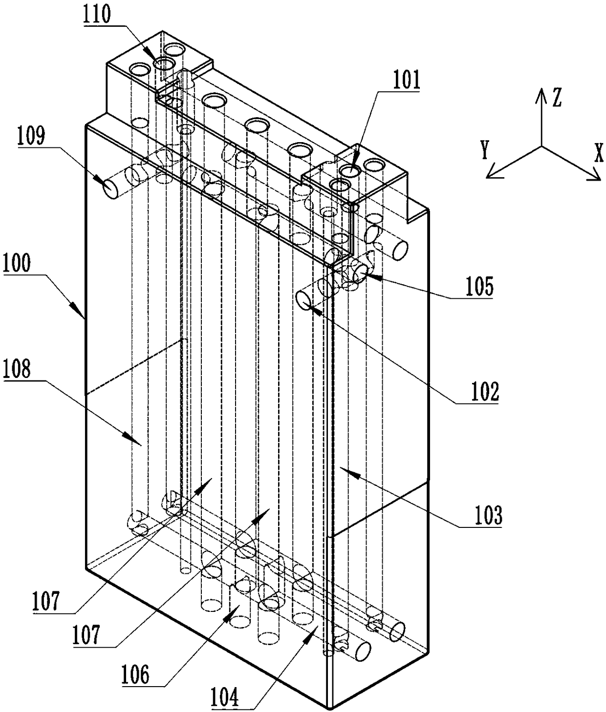
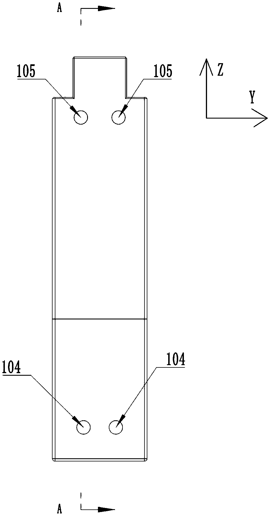
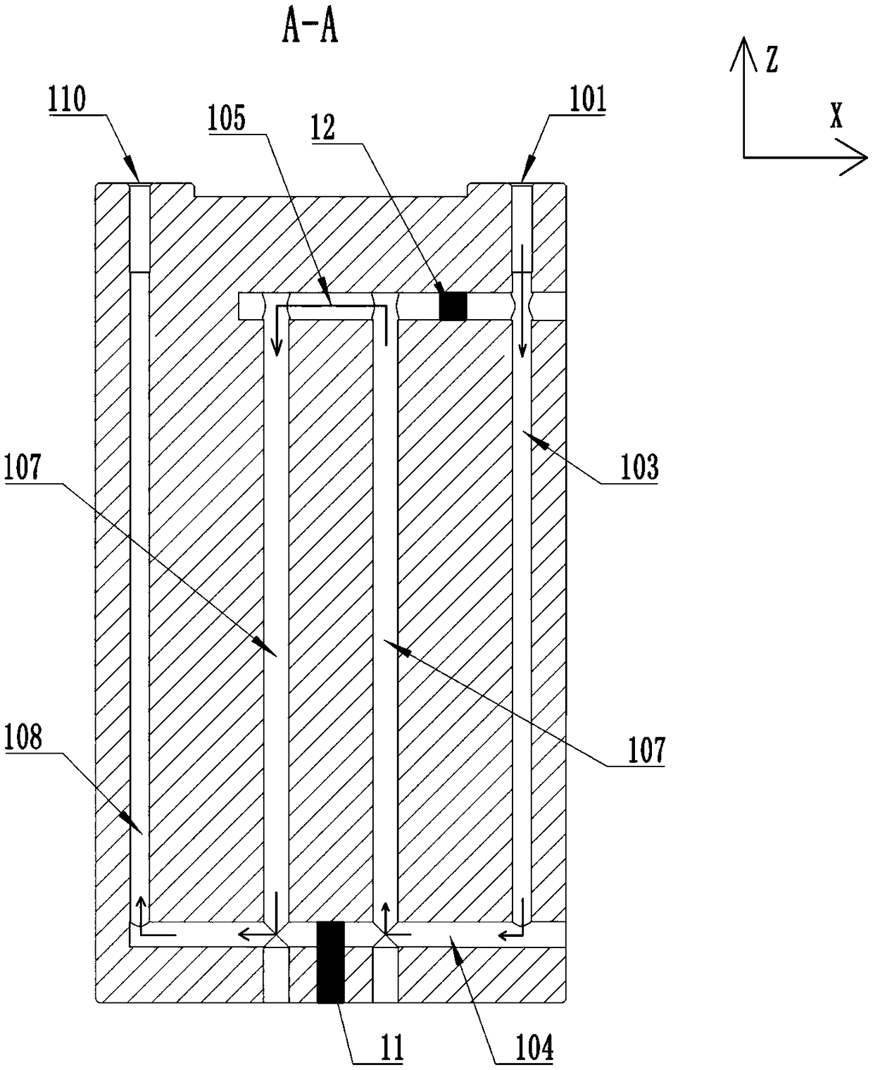
[0035] Please refer to Figure 1 to Figure 3 , a punch 10, including a punch body 100, a water inlet 101 and a water outlet 110 are respectively provided on opposite sides of the top surface of the punch body 100; The hole 102 and the water inlet 101 extend toward the inside of the punch body 100 along the Z-axis and communicate with the water inlet communication hole 102 .

[0036] In the punch body 100, along the water inlet communication hole 102, there are several water inlet holes 103 extending in the Z-axis direction at intervals in the axial direction, and several water inlet holes 103 are connected to the water inlet communication hole 102; each water inlet hole 103 The bottom ends communicate with the first water communication holes 104 extending in the X-axis direction respectively.

[0037] The first water passing hole 104 is distributed with a plurality of water passing holes 107 extending toward the Z-axis direction at intervals along its axial direction; the pun...

Embodiment 2

[0045] Please refer to Figure 5 , a stamping device, including the punch 10 described in the first embodiment above, the top of the punch 10 is fixedly connected with a stamping die handle 20, the stamping die handle 20 drives the punch 10 to move up and down, and the top of the stamping die handle 20 is fixedly connected with a stamping die handle 20. Die handle fixed plate 30.

[0046] A stamping template 50 is arranged directly below the bottom of the punch 10, and the stamping template 50 can drive the punch 10 to descend; Elastic punching rods 60 are provided.

[0047] Specifically, the stamping pin 60 includes an initial state and an elastic state. When the stamping pin 60 is not under pressure, it is the initial state. The top end of the stamping pin 60 is located in the punching groove 51. It becomes an elastic state, and when the pressure leaves, the punching pin 60 resets, and changes from an elastic state to an initial state.

[0048] The bottom end of the stamp...


PUM


Abstract

The invention discloses a punch. The punch comprises a punch body, a water inlet and a water outlet are formed in the top face of the punch body, the water inlet is communicated with a water inlet hole extending in the Z-axis direction, and the bottom of the water inlet hole is communicated with a first water through hole extending in the X-axis direction. A plurality of water holes formed in theZ-axis direction are distributed in the axial direction of the first water through hole at intervals, and the tops of the water holes are communicated with a second water through hole; one end of thefirst water through hole is communicated with the water inlet hole, the other end of the first water through hole is communicated with a water outlet hole extending in the Z-axis direction, and the water outlet is communicated with the water outlet hole; the first water through hole is internally blocked with a first blocking piece. By forming various communicated holes in the punch body, a plurality of heat dissipation flow channels are formed in the punch body, so that heat generated by squeezing and rubbing of a stamping die is brought away, and the punch body and the product are subjectedto heat dissipation.

Description

technical field [0001] The invention relates to the technical field of stamping, in particular to a punch and a stamping device. Background technique [0002] At present, in the manufacturing process of new energy power battery cases, stamping and stretching is an indispensable process equipment for stamping production, and it is a technology-intensive product. The quality, production efficiency and production cost of stamping parts are directly related to the design and manufacture of molds. The level of mold design and manufacturing technology is one of the important symbols to measure the level of a country's product manufacturing, which largely determines the quality, efficiency and new product development capabilities of products. The battery case stamping die is a tool for stamping made of metal and other steel materials, which includes a punch fixing plate, punch, stripping plate, concave template and other structures. During the working process, the stamping die is...

Claims


Application Information

Patent Timeline
Patent Type & Authority Applications(China)
IPC IPC(8): B21D37/16B21D37/10B21D45/10
CPCB21D37/10B21D37/16B21D45/10
Inventor 康天成邓银桥郑少涌
Owner 东莞市骏毅机电科技有限公司
Features
  • R&D
  • Intellectual Property
  • Life Sciences
  • Materials
  • Tech Scout
  • Unparalleled Data Quality
  • Higher Quality Content
  • 60% Fewer Hallucinations
Learn More