
Building cutting device and using method thereof

A cutting device and construction technology, applied in the direction of positioning device, clamping device, clamping, etc., can solve the problems of unsatisfactory use size, affecting cutting effect, and low cutting efficiency, so as to achieve convenient cutting position, automatic cutting process, The effect of high cutting efficiency

Inactive Publication Date: 2019-01-25
淮北辰威科技有限公司
View PDF3 Cites 12 Cited by
  • Summary
  • Abstract
  • Description
  • Claims
  • Application Information

AI Technical Summary

Problems solved by technology

[0002] During the construction process, the size of the existing profiles may not meet the size used, and some profiles need to be cut. The existing cutting device cannot fix the profiles, so the position of the profiles may be shifted during the cutting process. , affect the cutting effect, and require workers to manually adjust the position of the profile, which wastes a lot of labor and makes the cutting efficiency low. Therefore, we introduce a construction cutting device and its use method

Method used


Image

  • Building cutting device and using method thereof
  • Building cutting device and using method thereof
  • Building cutting device and using method thereof

Examples


Embodiment Construction

[0023] The following will clearly and completely describe the technical solutions in the embodiments of the present invention with reference to the accompanying drawings in the embodiments of the present invention. Obviously, the described embodiments are only some, not all, embodiments of the present invention. Based on the embodiments of the present invention, all other embodiments obtained by persons of ordinary skill in the art without making creative efforts belong to the protection scope of the present invention.

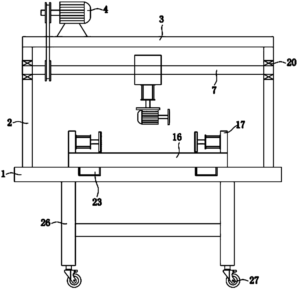
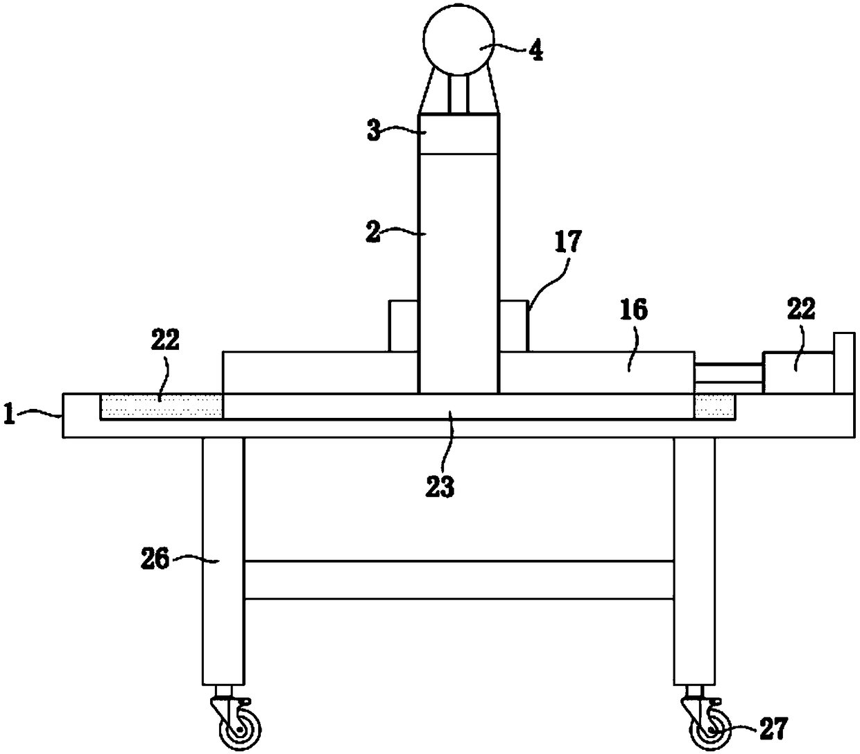
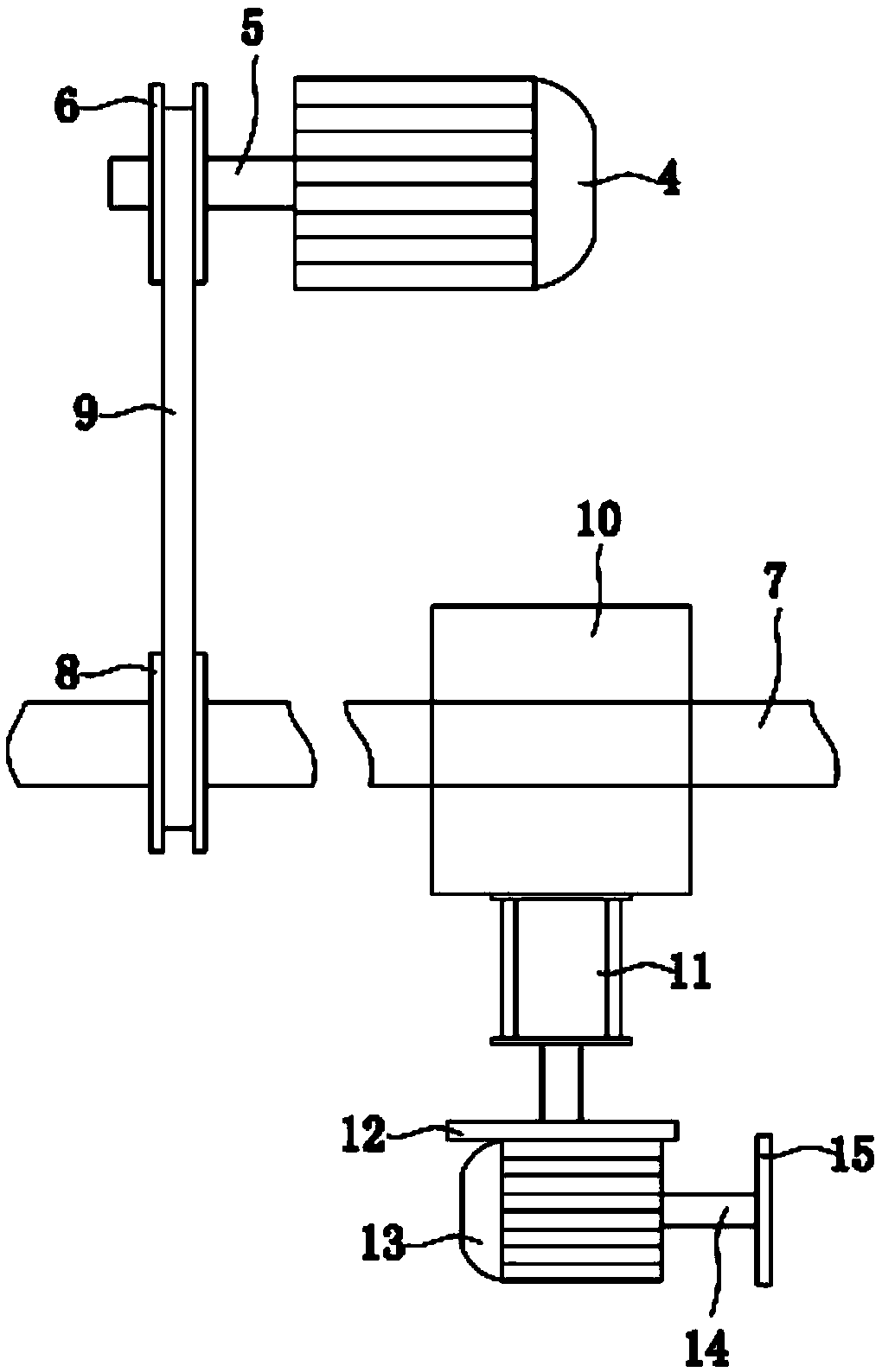
[0024] see Figure 1-4 , the present invention provides a technical solution: a building cutting device, including a workbench 1, the upper end of the workbench 1 is provided with a support plate 2 on the left and right sides, the upper end of the support plate 2 is provided with a top plate 3, and the top plate 3 A through hole is provided on the top plate 3, and a first motor 4 is provided on the left side of the upper end of the top plate 3. The output end ...


PUM


Abstract

The invention discloses a building cutting device. The building cutting device comprises a workbench, supporting plates are arranged at the left and right sides of the upper end of the workbench, a top plate is arranged at the upper ends of the supporting plates, a through hole is formed in the top plate, and a first motor is arranged at the left side of the upper end of the top plate; a first rotary shaft is arranged at the output end of the first motor, a driving belt pulley is arranged on the first rotary shaft, a lead screw is arranged at the lower end of the top plate, and a driven belt pulley is arranged on the lead screw; through outstretching and back-drawing of the output end of an air cylinder, an abutting plate is driven to move left and right, and thus materials are clamped toprevent the situation that the materials move in the cutting process and the cutting quality is influenced; through the arrangement of an antiskid rubber pad, the antiskid effect can be achieved; through outstretching and back-drawing of the output end of a second hydraulic cylinder, a placement plate can be driven to slide in a slide groove through a slide block, thus the placement plate moves front and back, and the positions of the materials and a cutting blade are convenient to adjust, so that the cutting process is more automatic; the cutting position is convenient to adjust, the labor ofworkers is reduced, and the working efficiency is improved.

Description

technical field [0001] The invention relates to the technical field of construction, in particular to a construction cutting device and a usage method thereof. Background technique [0002] During the construction process, the size of the existing profiles may not meet the size used, and some profiles need to be cut. The existing cutting device cannot fix the profiles, so the position of the profiles may be shifted during the cutting process. , affect the cutting effect, and require workers to manually adjust the position of the profile, which wastes a lot of labor and makes the cutting efficiency low. Therefore, we introduce a construction cutting device and its use method. Contents of the invention [0003] The object of the present invention is to provide a construction cutting device and its usage method, so as to solve the problems raised in the above-mentioned background technology. [0004] In order to achieve the above object, the present invention provides the fo...

Claims


Application Information

Patent Timeline
Patent Type & Authority Applications(China)
IPC IPC(8): B23D79/00B23Q3/08B23Q1/26
CPCB23D79/00B23Q1/26B23Q3/08B23Q2703/04
Inventor 王永辉王晓全
Owner 淮北辰威科技有限公司
Learn More