An unmanned aerial vehicle rotor structure and an unmanned aerial vehicle

A technology of rotor and aircraft, applied in the field of UAV rotor structure and UAV aircraft, to achieve the effect of simplifying the rotor structure and control logic and reducing the failure rate

Pending Publication Date: 2019-01-25
GOERTEK ROBTICS CO LTD
View PDF1 Cites 4 Cited by
  • Summary
  • Abstract
  • Description
  • Claims
  • Application Information

AI Technical Summary

Problems solved by technology

In order to achieve the single-direction reciprocating tilting of the bottom plate, the above structure generally requires two push rods uniformly distributed around the bottom plate to cooperate with each other. To realize the periodic pitch change in the circumferential direction, four push rods uniformly distributed around the bottom plate are required to cooperate with each other. implementation, increasing the complexity of the structure and control logic

Method used


Image

  • An unmanned aerial vehicle rotor structure and an unmanned aerial vehicle
  • An unmanned aerial vehicle rotor structure and an unmanned aerial vehicle
  • An unmanned aerial vehicle rotor structure and an unmanned aerial vehicle

Examples


Embodiment Construction

[0042] The following will clearly and completely describe the technical solutions in the embodiments of the present invention with reference to the accompanying drawings in the embodiments of the present invention. Obviously, the described embodiments are only some, not all, embodiments of the present invention. Based on the embodiments of the present invention, all other embodiments obtained by persons of ordinary skill in the art without making creative efforts belong to the protection scope of the present invention.

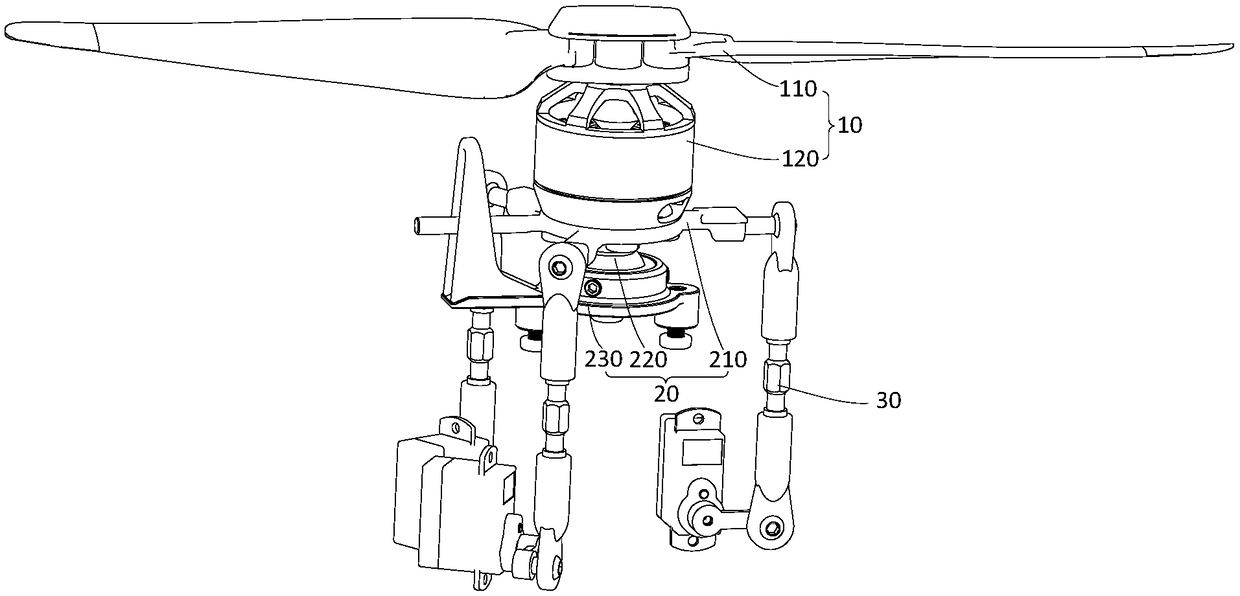
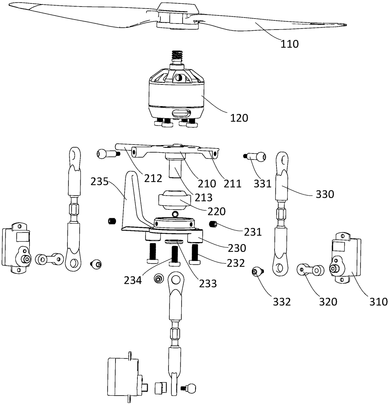
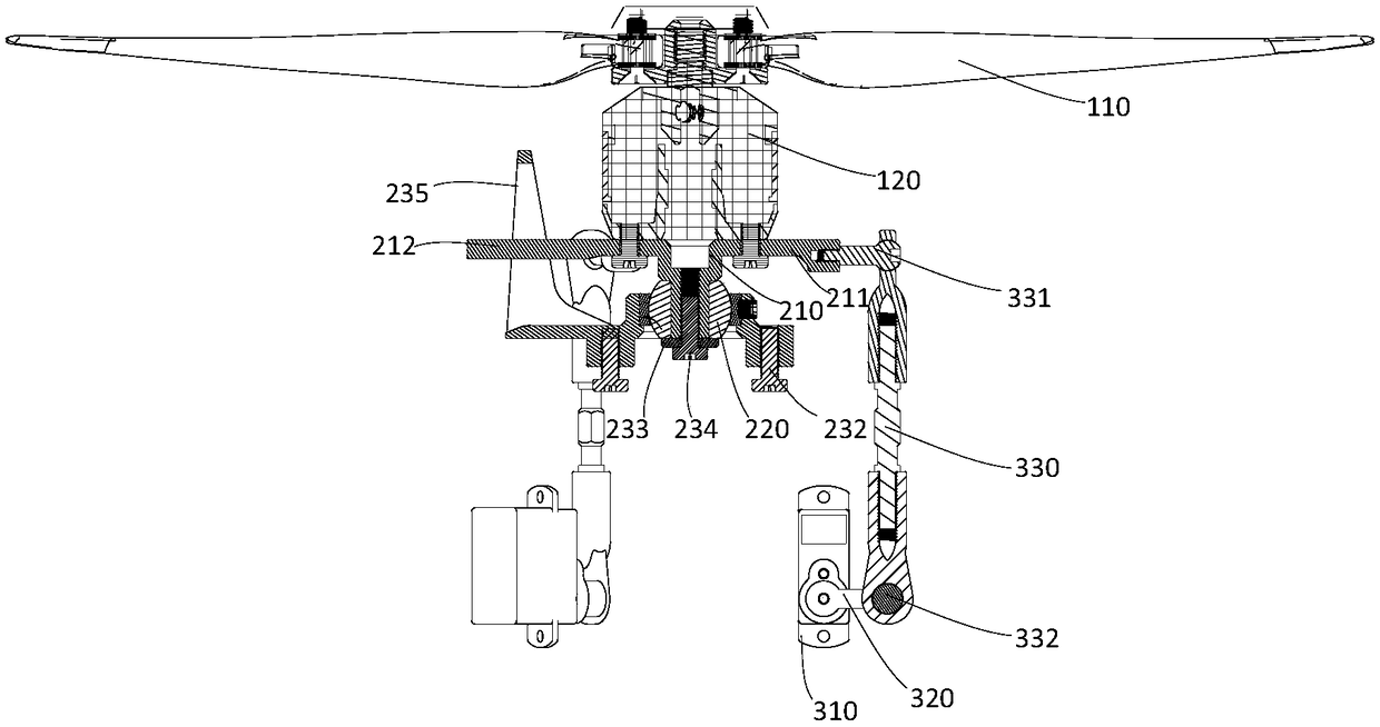
[0043] see Figure 1-Figure 3 , figure 1 The axonometric view of the UAV rotor structure provided by the embodiment of the present invention, figure 2 An exploded view of the UAV rotor structure provided by the embodiment of the present invention, image 3 It is a cross-sectional view of the UAV rotor structure provided by the embodiment of the present invention.

[0044] An unmanned aerial vehicle rotor structure provided by an embodiment of the present i...


PUM


Abstract

The invention discloses an unmanned aerial vehicle rotor structure and an unmanned aerial vehicle are disclose, the rotor structure of the unmanned aerial vehicle comprises a cross plate connecting assembly, a power connecting rod assembly and a rotor assembly, wherein, the cross plate connecting assembly comprises a cross tilting plate, an articulated bearing and a bracket, an outer ring of the articulated bearing is embedded in the bracket, and the articulated bearing is fixedly connected with the inner ring of the articulated bearing; the output end of the power connecting rod assembly is rotatably connected with the cross tilting plate; the rotor assembly comprises a main rotor and a driving device, wherein the driving device is used for driving the main rotor to rotate, and the driving device is arranged on a cross tilt plate; as for that rotor structure of the unmanned aerial vehicle, only one power connecting rod assembly is required to realize the reciprocating swing of the cross tilt plate in one direction, the rotor structure and control logic can be simplified, which helps to control the cost and reduce the failure rate.

Description

technical field [0001] The invention relates to the technical field of unmanned aerial vehicles, in particular to an unmanned aerial vehicle rotor structure and an unmanned aerial vehicle. Background technique [0002] At present, the single-rotor UAV generally uses an automatic swash plate to realize the steering of the UAV. The automatic swash plate is composed of upper and lower parts. The upper plate rotates with the rotor, and the lower plate does not rotate with the rotor. The upper plate is installed on the lower plate through bearings. The upper plate can rotate relative to the lower plate, and the lower plate drives the upper plate to tilt, and the upper plate changes the pitch of the rotor blades periodically through the connecting rod to realize the steering of the helicopter. In order to achieve the single-direction reciprocating tilting of the bottom plate, the above structure generally requires two push rods uniformly distributed around the bottom plate to coop...

Claims


Application Information

Patent Timeline
Patent Type & Authority Applications(China)
IPC IPC(8): B64C27/06B64C27/32
CPCB64C27/06B64C27/32
Inventor 牛锡亮卜凡利王晶
Owner GOERTEK ROBTICS CO LTD
Why Eureka
Try Eureka