Systems and methods for particulate filter regeneration

A particulate filter and torque converter technology, applied in the field of systems and methods for particulate filter regeneration, can solve problems such as reducing combustion stability

Pending Publication Date: 2019-01-25
FORD GLOBAL TECH LLC
View PDF1 Cites 2 Cited by
  • Summary
  • Abstract
  • Description
  • Claims
  • Application Information

AI Technical Summary

Problems solved by technology

As an example, extended operation of the engine with substantial spark retard from the MBT for exhaust heating purposes may result in increased variations in cylinder indicated mean effective pressure (IMEP), which may reduce combustion stability and trigger misfire monitor

Method used


Image

  • Systems and methods for particulate filter regeneration
  • Systems and methods for particulate filter regeneration
  • Systems and methods for particulate filter regeneration

Examples


Embodiment Construction

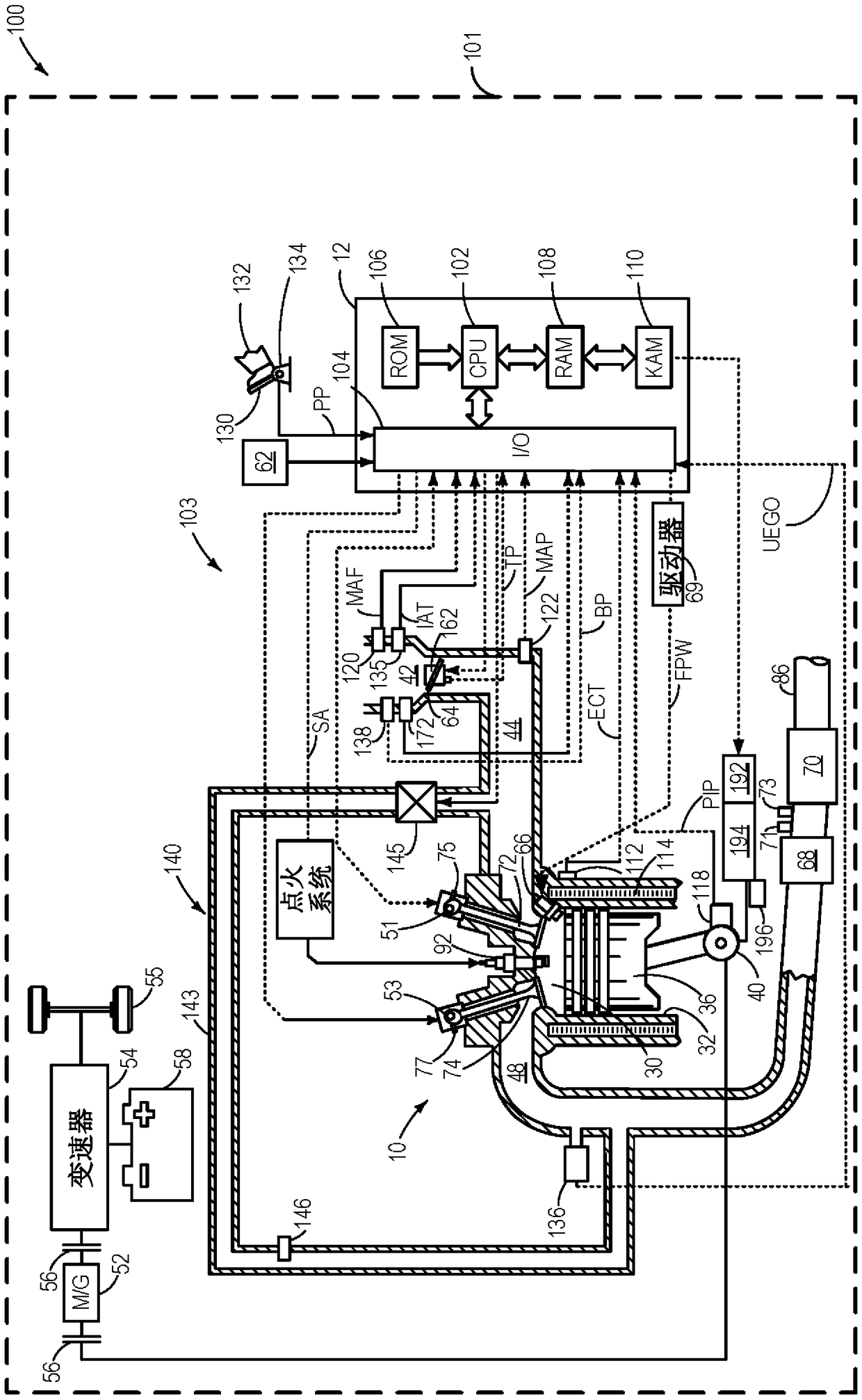
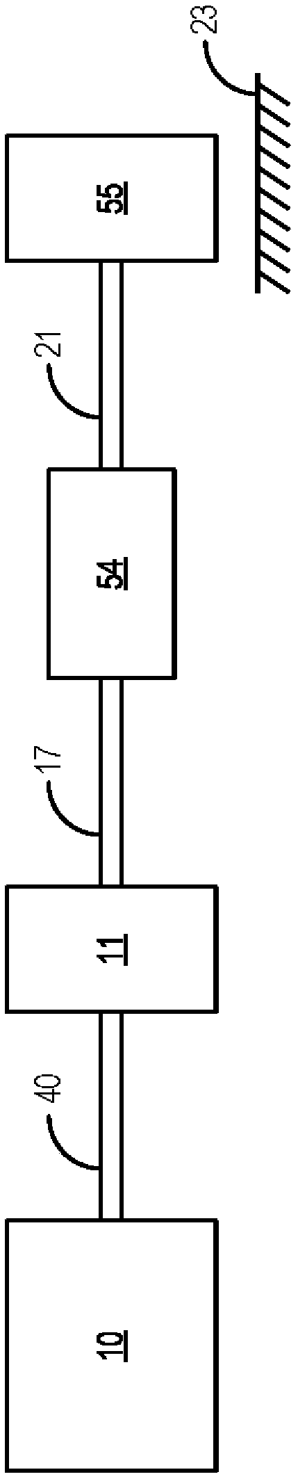
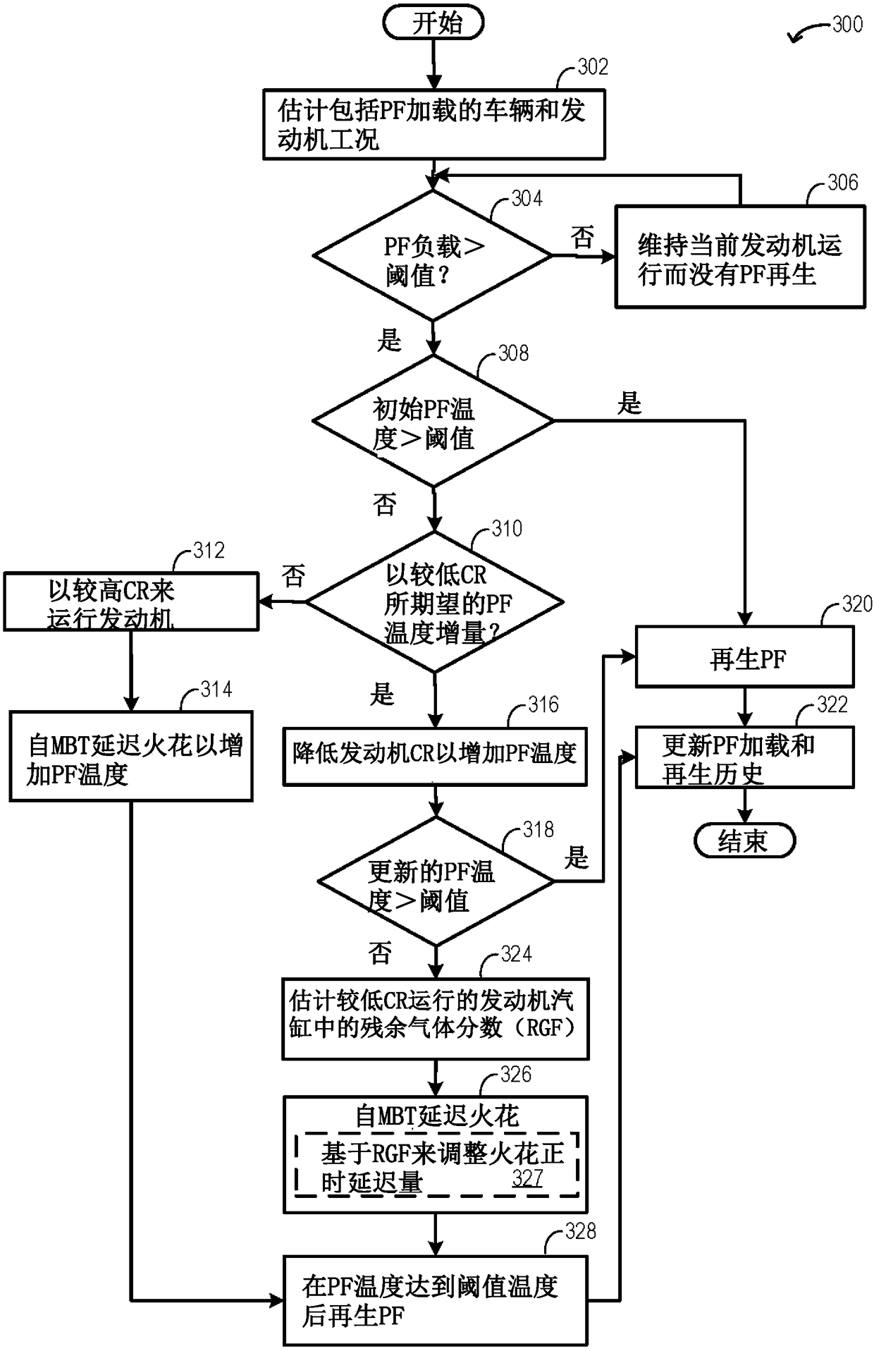
[0014] The following description relates to systems and methods for adjusting engine compression ratio and spark timing to increase filter temperature prior to initiating filter regeneration. figure 1 An example engine system including a particulate filter (PF) coupled to a hybrid vehicle is shown in . figure 2 An example of a vehicle driveline including a torque converter and a transmission system is shown in . The engine controller can be configured to execute control programs such as image 3 An example routine to coordinate adjustments to engine compression ratio with spark timing adjustments to increase PF temperature for PF regeneration. Figure 4 An example relationship between exhaust gas temperature and engine compression ratio is shown in . Figure 5 An example of coordinated adjustment of engine compression ratio and spark timing for increasing PF temperature is shown in .

[0015] figure 1 is a schematic diagram showing a vehicle system 100 including a vehicle...


PUM


Abstract

The invention relates to systems and methods for particulate filter regeneration. Methods and systems are provided for adjusting engine compression ratio (CR) and spark timing to attain particulate filter (PF) regeneration temperature. In one example, a method may include, in response to PF load reaching a threshold and PF temperature being lower than the PF regeneration temperature, lowering theCR and then selectively adjusting spark timing based on an estimated residual gas fraction (RGF) at the lower CR.

Description

technical field [0001] The present description generally relates to methods and systems for adjusting engine compression ratio and spark timing to achieve particulate filter regeneration temperatures. Background technique [0002] Engine combustion using gasoline fuel can generate particulate matter (PM), such as soot and aerosols, which can be emitted into the atmosphere. For emissions compliance, a particulate filter (PF) may be included in the engine exhaust to filter out exhaust PM before releasing the exhaust to the atmosphere. Such devices may be periodically or timely regenerated during engine operation to reduce the amount of trapped particulate matter. Regeneration is typically accomplished by raising the temperature of the PF to a predetermined level for a sustained period of time while flowing exhaust gas of a defined composition through the PF to combust or oxidize trapped particulate matter. [0003] Various methods are provided for regenerating PM in response...

Claims


Application Information

Patent Timeline
Patent Type & Authority Applications(China)
IPC IPC(8): F01N3/023F02D15/00F02D43/00
CPCF01N3/023F02D15/00F02D37/02F02D41/029F01N2430/08F02D41/0225F02D2200/0802F01N9/002F02D41/0245F02D41/1448F02D2200/0812Y02T10/12F01N3/0234F01N3/101F01N2430/06F02D41/0055F02D41/405
Inventor M·J·于里克J·N·尤瑞尔R·D·普尔斯福C·P·格鲁格拉E·G·塞尔班
Owner FORD GLOBAL TECH LLC
Why Eureka
Try Eureka