Hydraulic tool one-way valve and hydraulic tool

A hydraulic tool and one-way valve technology, applied in fluid pressure actuating devices, fluid pressure actuating system components, servo motors, etc., can solve problems such as insufficient sealing, reduced reliability, and low work efficiency, and achieve overcurrent The effect of high speed, improved reliability, and improved work efficiency

Pending Publication Date: 2019-01-25
TAIZHOU JULI TOOLS
View PDF11 Cites 2 Cited by
  • Summary
  • Abstract
  • Description
  • Claims
  • Application Information

AI Technical Summary

Problems solved by technology

[0003] For example, a hydraulic check valve [Application No.: 201420357673.8; Authorized Announcement No.: CN203948362U] proposed in Chinese patent documents, which consists of a ball holder, a steel ball, and a retaining ring. The cross-sectional diameter of the through hole is matched to radially limit the valve core, so that the valve core can always move along the axis of the body. Although the shortage of radial movement of the valve core after leaving the sealing surface is overcome, the It will still be affected by the gravity of the spool itself and the problem of insufficient sealing. After the spool leaves the sealing surface, it will often move radially and lean against the inner wall. The spring pushes the spool to move towards the sealing surface. At this time, the spherical The spool may leak when it is closed, causing the oil in the check valve to flow in reverse, resulting in low work efficiency and greatly reduced reliability

Method used


Image

  • Hydraulic tool one-way valve and hydraulic tool
  • Hydraulic tool one-way valve and hydraulic tool
  • Hydraulic tool one-way valve and hydraulic tool

Examples


Embodiment 1

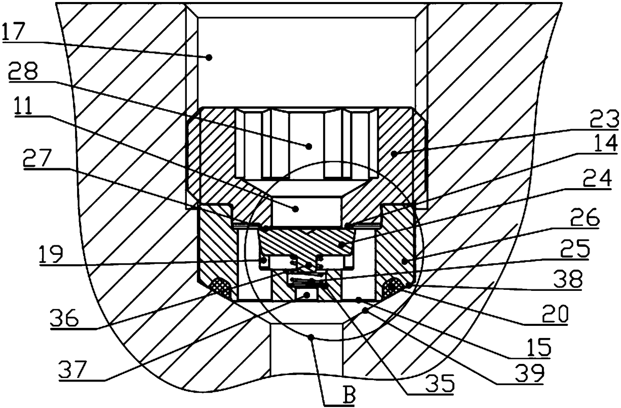
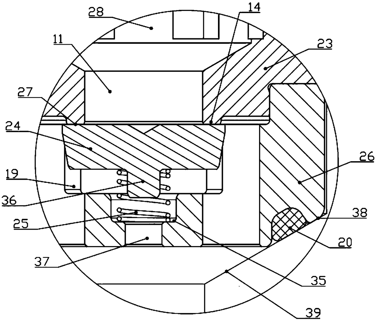
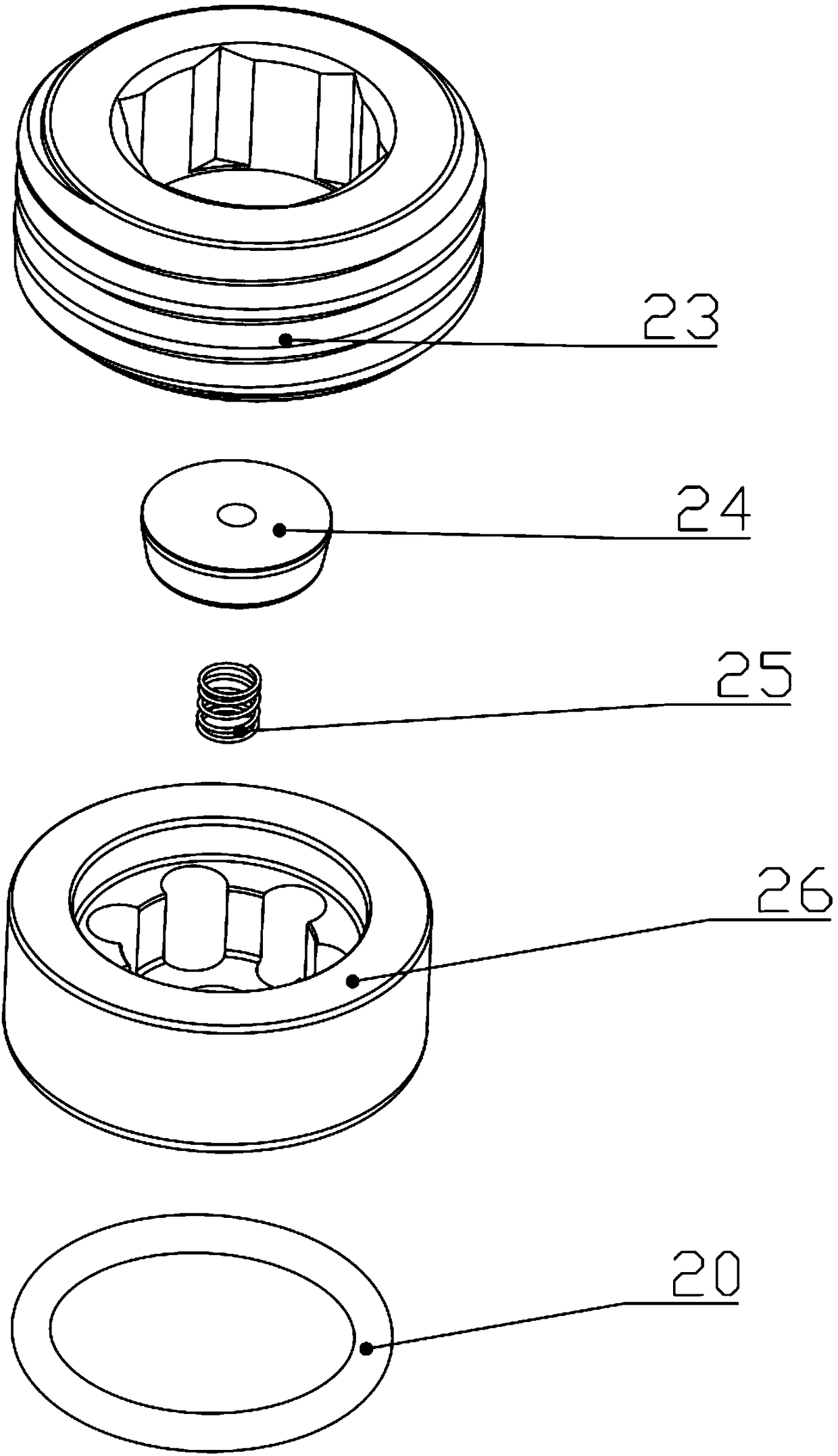
[0031] Embodiment one: if Figure 1-4 As shown, a check valve includes a valve seat 23 fixed in the valve hole 17, a valve body 26, and a valve core 24 and a spring 25 arranged between the valve seat 23 and the valve body 26. The valve seat 23 Open a through hole 11, the spring 25 abuts between the valve core 24 and the valve body 26, the lower end surface of the valve seat 23 is protruded with a boss 14, under the elastic force of the spring 25, the upper end of the valve core 24 The plane of the boss 14 can abut against the plane of the boss 14 and form a first sealing surface 27. The valve body 26 is provided with an inner side wall 19 that is suitable for the shape and size of the valve core 24, and the inner side wall 19 can be opposite to the The spool 24 is radially limited so that the spool 24 can always move along its axial direction, the bottom end of the valve seat 23 is provided with a through hole 11, and the bottom end of the valve body 26 is evenly distributed w...

Embodiment 2

[0047] Embodiment 2: This embodiment is basically the same as Embodiment 1, the difference is that, as Figure 5-7 As shown, the hydraulic check valve in this embodiment is used at the oil outlet of the pump core assembly 31, and the oil outlet check valve arranged in the oil outlet passage 3 includes an oil outlet valve body 7 and an oil outlet valve seat 8 , the oil outlet valve seat 8 is provided with an oil outlet 9, such as Figure 7 As shown, the upper end surface of the oil outlet valve seat 8 is an inclined surface, and an O-shaped sealing ring 20 is installed on the inclined surface, and the oil outlet valve seat 8 is squeezed on the tapered surface of the inner wall of the oil outlet valve hole by the O-shaped sealing ring 20 Form a seal, and the seal here is to prevent oil from rushing in from the oil outlet 9 to cause leakage. The oil enters the oil outlet valve seat 8 through the oil outlet 9 , pushes the spool 24 away, and the oil enters the flow channel 18 and ...


PUM


Abstract

The invention belongs to the technical field of hydraulic tools, and particularly relates to a hydraulic tool one-way valve and a hydraulic tool. The one-way valve comprises a valve seat and a valve body which are fixed in a valve hole and a valve core and a spring which are arranged between the valve seat and the valve body, the spring abuts against the valve core and the valve body, and the plane of the upper end of the valve core and the lower end face of the valve seat abut and form a first sealing face under the elasticity of the spring; a plurality of overflowing holes are uniformly distributed in the bottom of the valve body, when the upper end face of the valve core is separated from the lower end face of the valve seat, the overflowing holes are communicated with the through hole,and mediums in the through hole flows out from the overflowing holes. According to the one-way valve, the shape of the valve core is changed, plane sealing is adopted by the part between the valve core and the valve body, the sealing performance of the one-way valve is greatly improved by matching with the reduced sealing contacting face between the valve core and the valve body, and the oppositeposition oil returning of the one-way valve in the working process is prevented.

Description

technical field [0001] The invention belongs to the technical field of hydraulic tools, in particular to a check valve for hydraulic tools and hydraulic tools. Background technique [0002] At present, hydraulic tools, as a power component of a hydraulic system, include various types, among which electro-hydraulic tools generally include motors, oil storage chambers, hydraulic pumps, hydraulic cylinders, switch components, control valves, and hydraulic cylinders are equipped with return springs and When the piston rod and the electric hydraulic tool are working, the motor drives the hydraulic pump to rotate, press the pressure oil in the oil storage chamber into the hydraulic cylinder and push the hydraulic parts to make it in a working state, and suck the oil from the oil bag , and then the pressure oil is formed and then discharged until it is sent to the actuator for work; the core working part of the hydraulic tool is the pump body, and a valve hole is opened inside the ...

Claims


Application Information

Patent Timeline
Patent Type & Authority Applications(China)
IPC IPC(8): F15B13/02F15B11/08F15B21/041
CPCF15B11/08F15B13/027F15B21/041
Inventor 张银根何挺伟
Owner TAIZHOU JULI TOOLS
Why Eureka
Try Eureka