Furnace arch soot blowing system of boiler

A technology of soot blowing system and flame angle, which is applied to the treatment of combustion products, combustion methods, and removal of solid residues, etc. It can solve the problems of tube panel collision, high purge pressure, and high purge pressure of gas soot blowers. It achieves the effect of fast speed, high sound intensity and improved cleaning effect

Active Publication Date: 2019-01-25
伊思特(北京)能源科技有限公司
View PDF9 Cites 5 Cited by
  • Summary
  • Abstract
  • Description
  • Claims
  • Application Information

AI Technical Summary

Problems solved by technology

During the operation of the gas soot blower, the full stroke swings greatly, and it is easy to collide with the tube panel in the refraction angle area. It is easy to cause pipe explosion; the blowing pressure of the sonic soot blower is low, and there is basically no secondary dust effect on the coking-type ash accumulated on the slope of the flame angle, so that the coking-type ash cannot be taken away by the flue gas
[0004] In the Chinese patent with the publication number CN207555624U, a soot blowing system and a soot blowing method for the π-type boiler flame angle are disclosed. Through two purging processes of compressed air and steam, the upper slope of the flame angle is easy to clean. Dust deposits and hard-to-remove dust deposits are purged, and a good soot blowing effect is achieved through the composite purging mode, but the high purge pressure of the gas soot blower is still unavoidable. blowout problem

Method used


Image

  • Furnace arch soot blowing system of boiler
  • Furnace arch soot blowing system of boiler
  • Furnace arch soot blowing system of boiler

Examples


Embodiment Construction

[0032] The technical solutions of the present invention will be clearly and completely described below in conjunction with the accompanying drawings. Apparently, the described embodiments are some of the embodiments of the present invention, but not all of them. Based on the embodiments of the present invention, all other embodiments obtained by persons of ordinary skill in the art without making creative efforts belong to the protection scope of the present invention.

[0033] In the description of the present invention, it should be noted that the terms "center", "upper", "lower", "left", "right", "vertical", "horizontal", "inner", "outer" etc. The indicated orientation or positional relationship is based on the orientation or positional relationship shown in the drawings, and is only for the convenience of describing the present invention and simplifying the description, rather than indicating or implying that the referred device or element must have a specific orientation, ...


PUM


Abstract

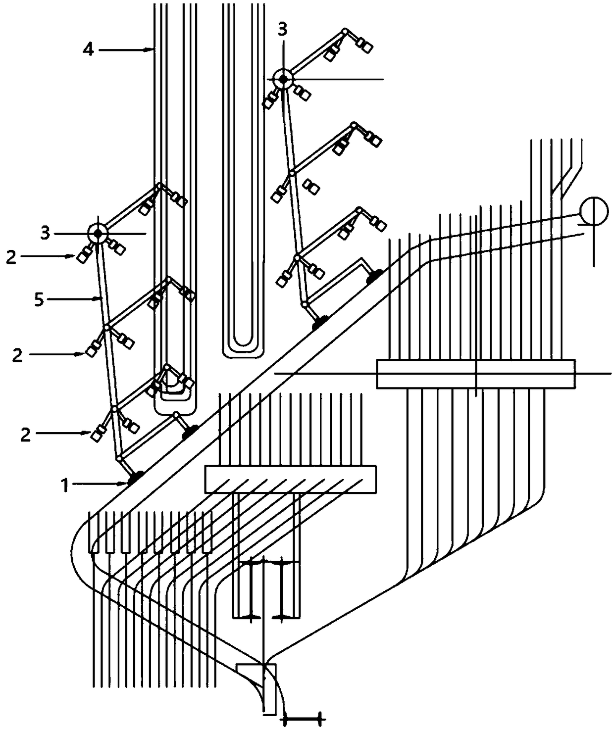
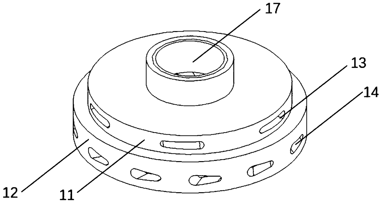
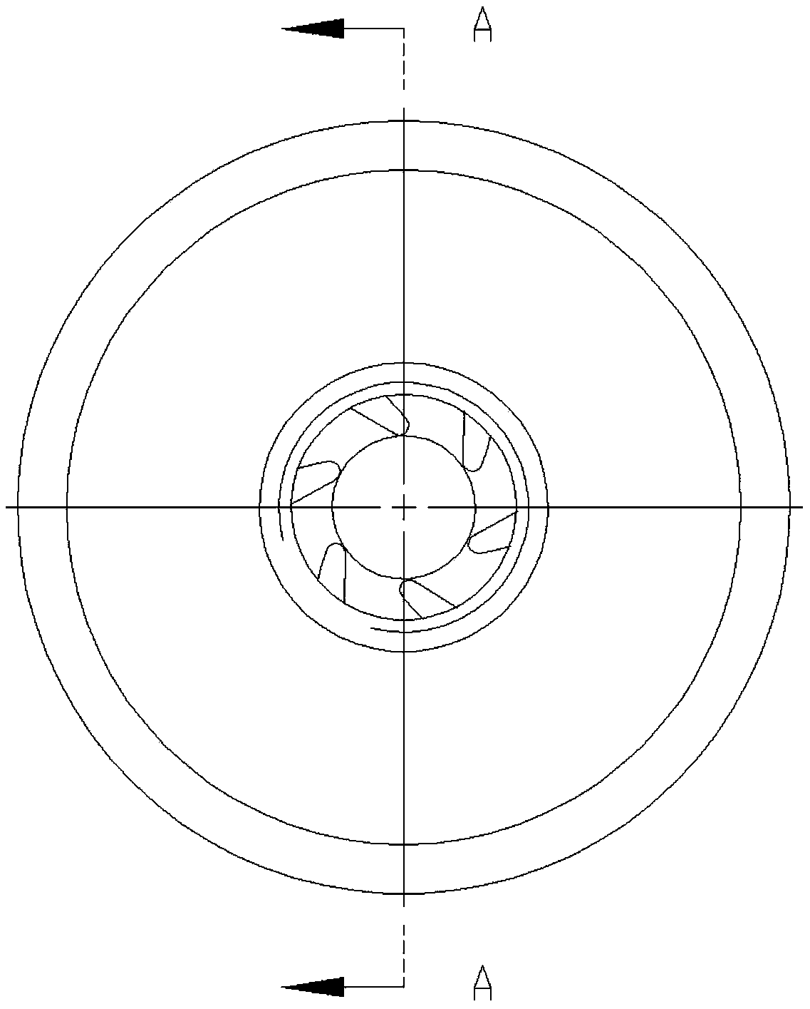
The invention relates to a furnace arch soot blowing system of a boiler. The system comprises multiple soot blowing units and soot blowing pipes extending into the boiler from soot blowing holes. Thesystem is characterized in that the soot blowing units are arranged on the soot blowing pipes, each first soot blowing unit comprises multiple coke dust collection soot blowers, each second soot blowing unit comprises high-strength sonic wave soot blowers, and the soot blowing units cooperate with one another for use. The soot blowers cooperate with one another for use, advantages of the soot blowers are fully utilized, and disadvantages of the soot blowers are avoided; at the same time, the structures of the coke dust collection soot blowers and the structures of the high-strength sonic wavesoot blowers are improved, the coke dust collection soot blowers change a direct-flow blowing mode into a vortex blowing mode, and blowing damage caused to high-temperature superheaters, final-stage reheaters and furnace arches is avoided; dry saturated steam or compressed air is pressurized and accelerated twice through spiral guide bodies and annular slits of the high-strength sonic wave soot blowers and then ejected out, so that the speed of air flow is higher, the sound intensity of formed sonic waves is higher, and the effect of removing dust on a boiler pipe can be further improved.

Description

technical field [0001] The invention relates to a soot blowing system used in a boiler, in particular to a soot blowing system for a boiler deflection angle. Background technique [0002] On the upper part of the back wall of the combustion chamber of some boilers, there is a triangular protrusion extending toward the furnace chamber. This triangular protrusion is called a refraction angle. Boilers with a "π" arrangement or a boiler with a "W" arrangement have a refraction angle. , there is a recirculation area on the upper part of the slope of the boiler flame angle, and the pressure in this area is obviously lower than that of other mainstream areas. Avoid separating and depositing it on the slope of the flame angle. Severe ash accumulation in the flame angle may cause the lower elbow of the high-temperature superheater to be buried in the ash pile, affecting the heat transfer effect. When the furnace is shut down, the pipe wall will be partially overheated, and a large a...

Claims


Application Information

Patent Timeline
IPC IPC(8): F23J1/00F23J3/02
CPCF23J1/00F23J3/02F23J2700/001
Inventor 刘亚玲
Owner 伊思特(北京)能源科技有限公司
Why Eureka
Try Eureka