Hole finding apparatus having integrated sensor and its method

A measurement device and wellbore technology, applied in electrical/magnetic detection, wellbore/well components, measurement, etc. for logging records, can solve problems such as incompatibility of technologies

Inactive Publication Date: 2002-10-16
SCHLUMBERGER OVERSEAS SA
View PDF4 Cites 2 Cited by
  • Summary
  • Abstract
  • Description
  • Claims
  • Application Information

AI Technical Summary

Problems solved by technology

however, current technologies for measuring the downhole environment

Method used


Image

  • Hole finding apparatus having integrated sensor and its method
  • Hole finding apparatus having integrated sensor and its method
  • Hole finding apparatus having integrated sensor and its method

Examples


Embodiment Construction

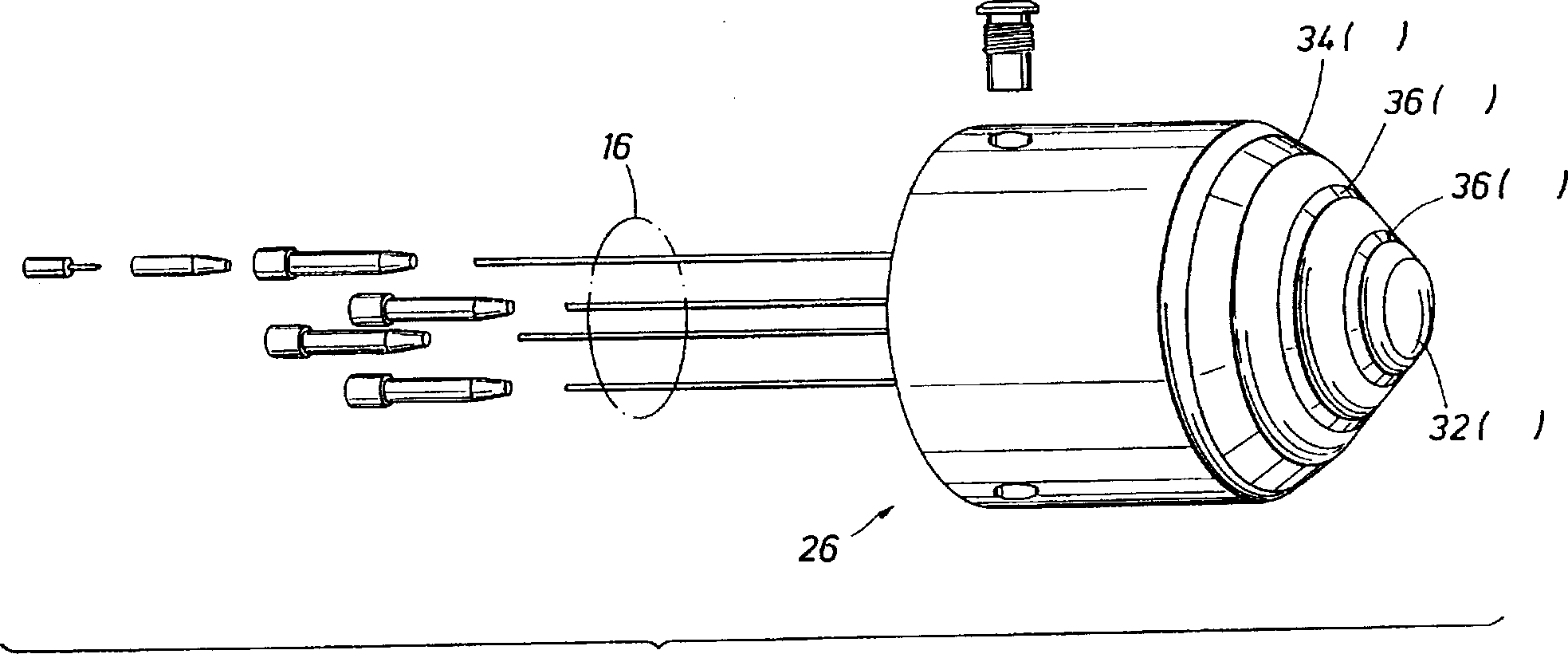
[0011] image 3 Shown is the probe described in US Pat. No. 5,574,371 to Tabanou et al., which may be incorporated into the tip of a wellbore sounding device. The disclosures of the above patents are hereby incorporated by reference. As shown in FIG. 4, the measurement probe 26 is firmly connected and bonded to the bottom (ie, the end) of the borehole detection device. For ease of description, this application is shown in image 3 The measuring probe 26 in to 5 bears the same reference numerals as the measuring probe in Fig. 5 of this US Pat. No. 5,574,371. The measuring probe 26 is suitable for use in filling mud boreholes to measure the natural potential Sp of the mud and the resistivity Rm of the liquid. When the logging instrument is placed in the borehole, the measurement probe 26 includes: a bottom electrode 32 (A 0 ), a second electrode 34 (A 1 ), and at least one placed on the bottom electrode 32 (A 0 ) nearby and used to measure the potential drop of a region of...


PUM


Abstract

Measuring or detecting drilling fluid or formation environment by using electrical, acoustic, mechanical or nuclear devices while conducting borehole detection or during detection. The borehole detection device equipped with an integral sensor of the present invention can effectively combine the measurement or detection capability of the downhole or formation environment either internally (such as by using a nuclear source/sensor) or as part of a borehole detection instrument, so that The device can provide mechanical and detection functions simultaneously or continuously. In the embodiment, a group of electrodes is installed as a probe at the end of the borehole detection device, so that it can measure the drilling fluid resistivity Rm and the natural potential Sp when guiding the equipment through the borehole.

Description

technical field [0001] The present invention relates to logging tools incorporating borehole detection devices. Background technique [0002] Borehole detection using a device with transverse elastic properties at the bottom of the tool or equipment is a common occurrence in the logistics of downhole surveys. Such devices are typically fabricated from homogenous elastomers or other similar elastic materials. Such as figure 1 A basic form of the device is smooth, with a withdrawn profile, uniformly increasing in cross-section adjacent the instrument or equipment, as shown in Figure 2, to provide a more rigid bending moment against lateral deflection towards the tool tip. Variations in material selection, cross-sectional profile, length and application of protrusions are possible. Regardless of the specific mechanical design of such a device, the purpose of the device is to guide equipment or instrumentation into a subterranean borehole to its intended location, regardless ...

Claims


Application Information

Patent Timeline
IPC IPC(8): E21B23/14E21B47/01G01V11/00G01V3/18
CPCE21B23/14G01V3/18G01V11/002E21B47/017
Inventor S·R·汤马斯G·A·哈泽
Owner SCHLUMBERGER OVERSEAS SA
Why Eureka
Try Eureka