A thermal management system for a hydrogen fuel cell vehicle

A thermal management system and fuel cell technology, applied in fuel cells, electric energy management, electric vehicles, etc., can solve problems such as uncontrollable conductivity of coolant, low heat exchange volume of the main circulation loop, and inability to control the circulation volume of coolant

Active Publication Date: 2021-07-30
CHERY AUTOMOBILE CO LTD
View PDF5 Cites 0 Cited by
  • Summary
  • Abstract
  • Description
  • Claims
  • Application Information

AI Technical Summary

Problems solved by technology

[0005] Although the thermal management system of hydrogen fuel cell electric vehicles in the prior art has a deionizer in the coolant circulation circuit to remove conductive ions in the coolant, this setting cannot control the circulation volume of the coolant, so that the cooling The conductivity of the liquid is uncontrollable. At the same time, due to the high resistance of the deionizer, the heat exchange volume of the main circulation loop is low, and the energy consumption of the system is large.

Method used


Image

  • A thermal management system for a hydrogen fuel cell vehicle
  • A thermal management system for a hydrogen fuel cell vehicle
  • A thermal management system for a hydrogen fuel cell vehicle

Examples


Embodiment 1

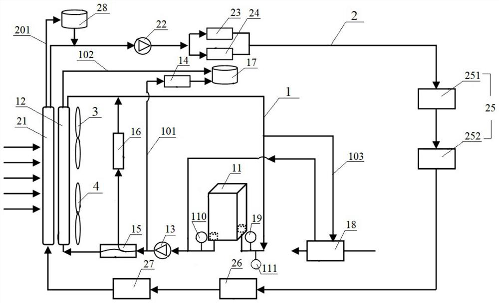
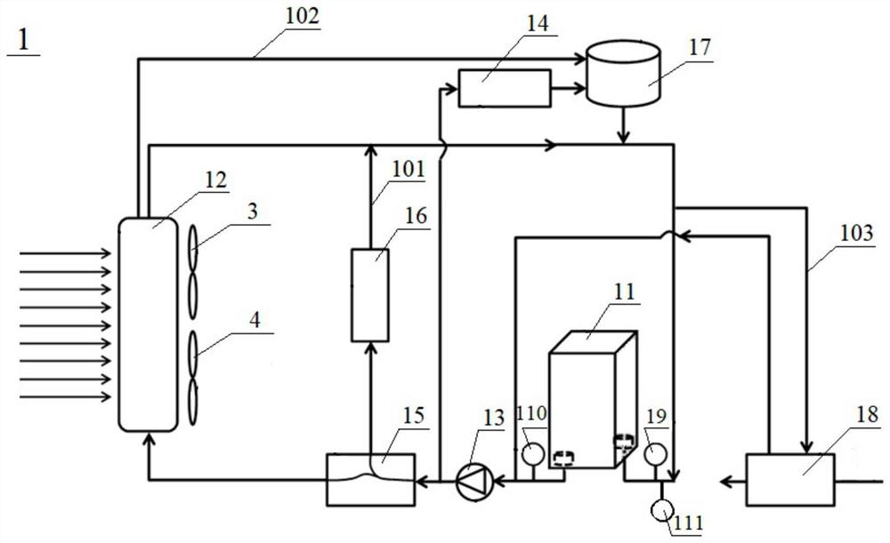
[0127] This embodiment provides a thermal management system for a hydrogen fuel cell vehicle, including a first cooling circuit 1 and a second cooling circuit 2 .

[0128] For the first cooling circuit 1, the first radiator 12, the first temperature sensor 19, the pressure sensor 111, the 36kW hydrogen fuel stack 11, the second temperature sensor 110, the circulation pump 13, the After the thermostat 15 is connected in series to form the main circulation loop, the heater 16, the first branch 101 provided with the deionizer 14, the second branch 102 provided with the first expansion tank 17, and the intercooler 18 are respectively installed. The third branch 103 of . Wherein, the ion exchange capacity of the deionizer 14 is 200meq / g, and the cooling liquid circulation volume of the first branch 101 is 5% of the cooling liquid circulation volume of the main circulation loop.

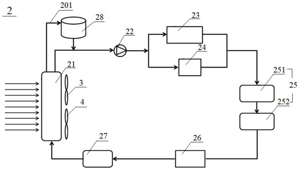
[0129] For the second cooling circuit 2, the second radiator 21, electronic water pump 22, air compres...

Embodiment 2

[0137] This embodiment provides a thermal management system for a hydrogen fuel cell vehicle, including a first cooling circuit 1 and a second cooling circuit 2 .

[0138]For the first cooling circuit 1, the first radiator 12, the first temperature sensor 19, the pressure sensor 111, the 36kW hydrogen fuel stack 11, the second temperature sensor 110, the circulation pump 13, the After the thermostat 15 is connected in series to form the main circulation loop, the heater 16, the first branch 101 provided with the deionizer 14, the second branch 102 provided with the first expansion tank 17, and the intercooler 18 are respectively installed. The third branch 103 of . Wherein, the ion exchange capacity of the deionizer 14 is 330meq / g, and the cooling liquid circulation volume of the first branch 101 is 5% of the cooling liquid circulation volume of the main circulation loop.

[0139] For the second cooling circuit 2, the second radiator 21, electronic water pump 22, air compress...

Embodiment 3

[0147] This embodiment provides a thermal management system for a hydrogen fuel cell vehicle, including a first cooling circuit 1 and a second cooling circuit 2 .

[0148] For the first cooling circuit 1, the first radiator 12, the first temperature sensor 19, the pressure sensor 111, the 36kW hydrogen fuel stack 11, the second temperature sensor 110, the circulation pump 13, the After the thermostat 15 is connected in series to form the main circulation loop, the heater 16, the first branch 101 provided with the deionizer 14, the second branch 102 provided with the first expansion tank 17, and the intercooler 18 are respectively installed. The third branch 103 of . Wherein, the ion exchange capacity of the deionizer 14 is 490meq / g, and the cooling liquid circulation volume of the first branch 101 is 5% of the cooling liquid circulation volume of the main circulation loop.

[0149] For the second cooling circuit 2, the second radiator 21, electronic water pump 22, air compres...


PUM

PropertyMeasurementUnit
electrical conductivityaaaaaaaaaa

Abstract

The invention discloses a thermal management system for a hydrogen fuel cell vehicle, comprising a first cooling circuit (1) and a second cooling circuit (2), the first cooling circuit (1) is for cooling a hydrogen fuel cell stack (11), and the first The cooling circuit (1) is provided with a first radiator (12), a hydrogen fuel stack (11) and a circulation pump (13); the first cooling circuit (1) includes a first branch provided with a deionizer (14) road (101); the second cooling circuit (2) is used to cool the hydrogen fuel cell auxiliary system and the electric drive system, and the second cooling circuit (2) is provided with a second radiator (21), an electronic water pump (22), an air compressor machine drive motor (23), air compressor controller (24), DC / DC converter (25), motor controller (26) and vehicle drive motor (27); the first radiator (12) and the second radiator The devices (21) are arranged in series in the traveling direction of the vehicle. The system has the characteristics of good heat dissipation effect and controllable conductivity of hydrogen fuel cell coolant.

Description

technical field [0001] The invention relates to the technical field of new energy vehicles, in particular to a heat management system for a hydrogen fuel cell vehicle. Background technique [0002] A hydrogen fuel cell is a power generation device that converts chemical energy into electrical energy by electrochemically reacting hydrogen with oxygen in the air. Its power generation efficiency is generally around 50%. It is beneficial to the electrochemical reaction, but it will also have an adverse effect on the life of the proton exchange membrane. If the control is unreasonable, it will cause water flooding or the proton membrane to dry up, which will adversely affect the performance of the hydrogen fuel cell. Therefore, it is very necessary for electric vehicles to thermally manage the hydrogen fuel cells inside them. [0003] At present, the thermal management system of hydrogen fuel cell electric vehicles uses a deionizer in the coolant circulation loop to remove condu...

Claims


Application Information

Patent Timeline
Patent Type & Authority Patents(China)
IPC IPC(8): B60L58/33H01M8/04029
CPCH01M8/04029Y02E60/50Y02T10/72Y02T90/40
Inventor 陈大华潘立升
Owner CHERY AUTOMOBILE CO LTD
Why Eureka
Try Eureka