Heat exchanger, heat dissipation method for heat exchanger and communication equipment

A technology for heat exchangers and communication equipment, which is applied in the field of heat exchangers and communication equipment, and can solve problems such as difficulty in meeting the heat dissipation requirements of communication equipment and large flow resistance

Inactive Publication Date: 2010-10-27
HUAWEI TECH CO LTD
View PDF4 Cites 10 Cited by
  • Summary
  • Abstract
  • Description
  • Claims
  • Application Information

AI Technical Summary

Problems solved by technology

[0006] The plate heat exchange core 11 in the prior art is composed of partitions, the air outside the communication equipment flows through the second air passage 13 of the plate heat exchange core 11 and the air in the communication equipment flows through the second air duct 13 of the plate heat exchange core 11. When the first air duct is 15, the flow resistance is relatively large. In this way, with the increase of the power of the communication equipment, it may be difficult to meet the heat dissipation requirements of the communication equipment by using the plate heat exchange core.

Method used


Image

  • Heat exchanger, heat dissipation method for heat exchanger and communication equipment
  • Heat exchanger, heat dissipation method for heat exchanger and communication equipment
  • Heat exchanger, heat dissipation method for heat exchanger and communication equipment

Examples


Embodiment 1

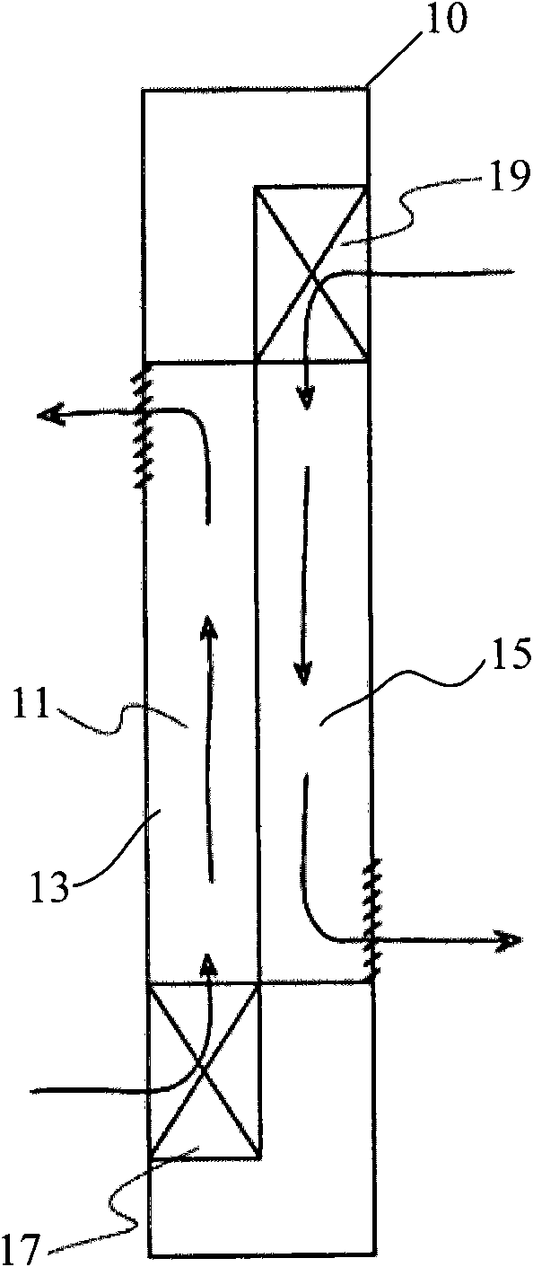
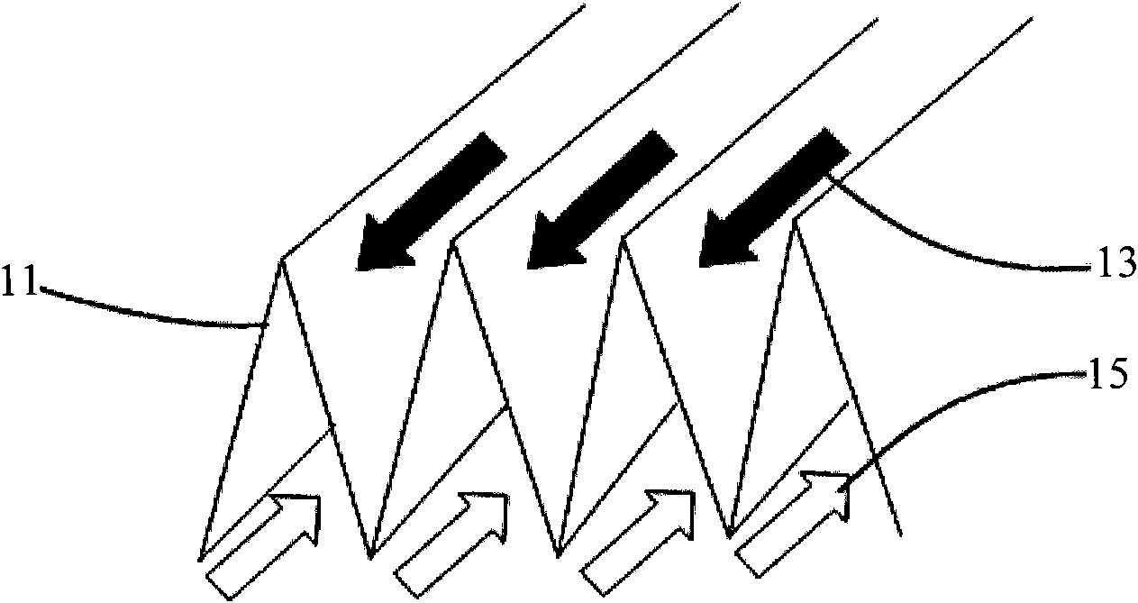
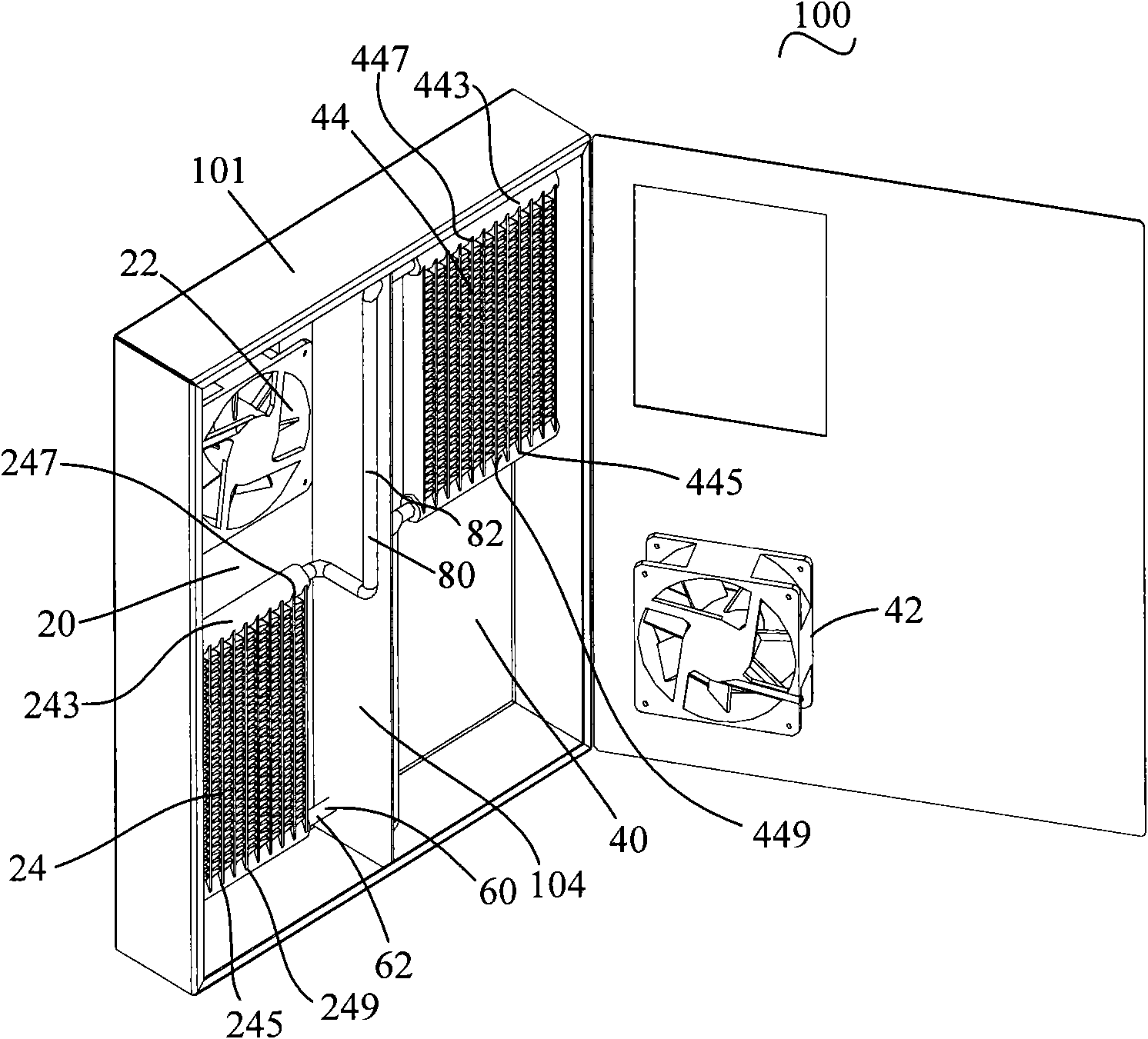
[0031] see image 3 , Figure 6 and Figure 7 ,in, image 3 It is a schematic diagram of a three-dimensional structure of a heat exchanger according to an embodiment of the present invention, Figure 6 is the schematic diagram of the first group of heat dissipation thin tubes, Figure 7 for Figure 6 The partial enlarged schematic diagram of A. The heat exchanger 100 includes a first air duct 20 and a second air duct 40, the first air duct 20 and the second air duct 40 are isolated from each other, wherein the first air duct 20 is provided with a first fan unit 22 and The first group of heat dissipation thin tubes 24; the second air duct 40 is provided with a second fan unit 42 and a second group of heat dissipation thin pipes 44; the upper end 247 of the first group of heat dissipation thin pipes 24 passes through the steam confluence pipe 80 and The upper end 447 of the second group of heat dissipation thin tubes 44 communicates with the lower end 449 of the first grou...

Embodiment 2

[0072] see Figure 11 , is a schematic diagram of a heat dissipation method of a heat exchanger in an embodiment of the present invention.

[0073] The heat dissipation method of the heat exchanger includes:

[0074] Step 201: The air inside the communication device flows through the first air channel under the action of the first fan unit, and the air outside the communication device flows through the second air channel under the action of the second fan unit, wherein the first air channel and the The second air ducts are isolated from each other;

[0075] Step 202: The air in the communication device flowing through the first air channel exchanges heat with the liquid in the first group of heat dissipation thin tubes, so that the liquid in the first group of heat dissipation thin tubes absorbs heat and evaporates into steam, and the steam moves along the The steam confluence pipe flows to the second group of heat dissipation thin tubes;

[0076] Step 203: The air outside ...

Embodiment 3

[0080] The embodiment of the present invention also provides a communication device, the communication device includes a heat exchanger 100 and a cabinet, a single board is arranged in the cabinet, and the heat exchanger 100 is arranged in the cabinet, wherein, please refer to image 3 , the heat exchanger 100 includes a first air duct 20 and a second air duct 40, the first air duct 20 and the second air duct 40 are isolated from each other, and the first air duct 20 communicates with the air in the cabinet (can forming an inner circulation air duct), the second air duct 40 communicates with the air outside the cabinet (can form an outer circulation air duct), wherein, the first air duct 20 is provided with a first fan unit 22 and a first group of cooling cells Pipe 24; the second air duct 40 is provided with a second fan unit 42 and a second group of heat dissipation thin tubes 44; the upper end 247 of the first group of heat dissipation thin pipes 24 along the direction of gr...


PUM


Abstract

The embodiment of the invention provides a heat exchanger, a heat dissipation method for the heat exchanger and communication equipment. The heat exchanger comprises a first air flue and a second air flue; the first air flue and the second air flue are mutually isolated; the first air flue is provided with a first fan unit and a first group of heat dissipation thin tubes; the second air flue is provided with a second fan unit and a second group of heat dissipation thin tubes; the upper ends of the first group of heat dissipation thin tubes along the gravity direction are communicated with the upper ends of the second group of heat dissipation thin tubes along the gravity direction through steam confluence tubes, and the lower ends of the first group of heat dissipation thin tubes along the gravity direction are communicated with the lower ends of the second group of heat dissipation thin tubes along the gravity direction through liquid confluence tubes; the first group of heat dissipation thin tubes, the steam confluence tubes, the second group of heat dissipation thin tubes and the liquid confluence tubes form a closed pipeline; and heat vaporization liquid is filled in the closed pipeline, radiating fins are arranged between the heat dissipation thin tubes of the first group, and radiating fins are arranged between the heat dissipation thin tubes of the second group. The flow resistance of airflow flowing through the heat dissipation thin tubes is low so as to well meet the heat dissipation requirement of the communication equipment.

Description

technical field [0001] The invention relates to the technical field of heat dissipation, in particular to a heat exchanger, a heat dissipation method for the heat exchanger, and communication equipment. Background technique [0002] With the development of communication technology, the integration of communication equipment is getting higher and higher, and the heat consumption per unit space is also increasing. At the same time, in order to meet the needs of the market in the communication field, the application fields of communication equipment are becoming wider and wider. For outdoor communication equipment, the most notable feature is that the communication equipment can adapt to different regional environments, and can also adapt to the temperature of different regional environments. Therefore, outdoor communication equipment should be able to solve the heat dissipation problem of communication equipment in different regions and different environments. [0003] see ...

Claims


Application Information

Patent Timeline
Patent Type & Authority Applications(China)
IPC IPC(8): F28D15/04F28F1/32F28F9/02H05K7/20
CPCF28D15/0266H05K7/202G06F1/20
Inventor 冯踏青洪宇平林辉彭锋张运辉吴琼
Owner HUAWEI TECH CO LTD
Why Eureka
Try Eureka