
Novel anchoring piece, cast-in-place wall containing steel wire mesh frame plate and construction technology of cast-in-place wall

The technology of steel wire mesh frame and anchor is applied in the field of building structure thermal insulation, which can solve the problems of difficult construction and low efficiency, and achieve the effects of easy promotion and use, simple process and convenient installation.

Pending Publication Date: 2019-01-29
JINAN JIEYUAN NEW MATERIAL CO LTD
View PDF10 Cites 7 Cited by
  • Summary
  • Abstract
  • Description
  • Claims
  • Application Information

AI Technical Summary

Problems solved by technology

[0004] The patent application document discloses the connecting support positioning parts used to control the distance between the structural layers of the composite wall system. During installation, the steel wire mesh frame plate construction needs to be completed before the installation of the anchors on both sides. The installation requires people on both sides And at the same time closely cooperate with the construction, and need to climb the heights, the construction cooperation is difficult, the efficiency is low, and there is a certain risk

Method used


Image

  • Novel anchoring piece, cast-in-place wall containing steel wire mesh frame plate and construction technology of cast-in-place wall
  • Novel anchoring piece, cast-in-place wall containing steel wire mesh frame plate and construction technology of cast-in-place wall
  • Novel anchoring piece, cast-in-place wall containing steel wire mesh frame plate and construction technology of cast-in-place wall

Examples


Embodiment 1

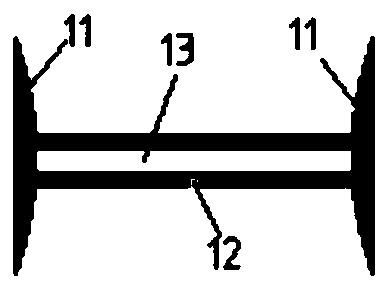
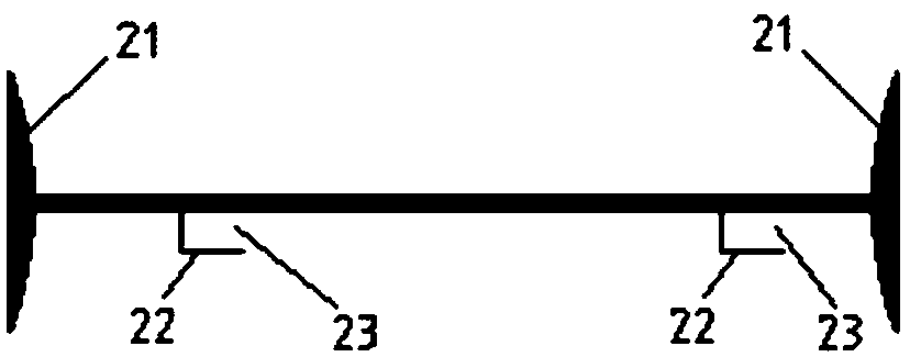
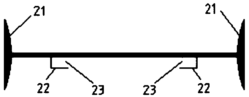
[0043] as attached figure 1 , 2a , 2b, this embodiment describes a new type of anchor, which is composed of two components, namely the first component 1 and the second component 2, the first component is used to be installed on the steel wire mesh sheet outside the steel wire grid insulation board, To prevent the wire grid insulation board from shifting into the first cast-in-place structure, the second member 2 is used to install on the shear wall reinforcement, which not only prevents the wire grid insulation board from shifting into the second cast-in-place structure, but also Effectively fix the reinforcement of the shear wall without displacement, and ensure the thickness of the protective layer of the reinforcement of the shear wall.

[0044] figure 1 A schematic diagram showing the structure of the first member 1. The middle part of the first member 1 has a support rod, and the left and right ends of the support rod are provided with first trays 11 . Among them, the...

Embodiment 2

[0057] Such as image 3 As shown, this embodiment describes a cast-in-place wall with steel wire grid panels.

[0058] It includes wire mesh frame board 3 . The steel wire mesh frame plate 3 includes a thermal insulation board 31, the outer side of the thermal insulation board 31 is a first cast-in-place structure 32, the first cast-in-place structure 32 is provided with a steel wire mesh sheet 34, and the inner side of the thermal insulation board 31 is a second cast-in-place structure 33, Insulation board 31 is provided with abdominal wire 35, and described abdominal wire 35 passes through insulation board 31, and one end of abdominal wire 35 is connected with described steel mesh sheet 34, and the other end extends into described second cast-in-place structure 33;

[0059] A number of horizontal bars of the shear wall, the number of horizontal bars of the shear wall are arranged in the second cast-in-place structure 33;

[0060] Also includes: multiple novel anchors descr...

Embodiment 3

[0066] The construction technique of the cast-in-place wall body containing the steel wire grid plate 3 described in embodiment 2 comprises the following steps:

[0067] (1) Binding the shear wall reinforcement, when binding the shear wall horizontal reinforcement, the second component 2 is directly stuck on the reinforcement;

[0068] (2) Install the first component 1: install the first component 1 on the steel wire mesh sheet 34 outside the steel wire grid plate 3 in advance;

[0069] (3) steel wire mesh frame plate 3 is installed;

[0070] (4) Install the outer formwork 36 and the inner formwork 37 so that the outer formwork 36 is offset against the first pallet 11, and the inner formwork 37 is offset against the second pallet 21;

[0071] (5) Pouring concrete;

[0072] Steps (1) and (2) have no chronological order.

[0073] In the construction process of this embodiment, the anchors can be directly snapped into the horizontal bars of the shear wall when the reinforcemen...


PUM


Abstract

The invention discloses a novel anchoring piece, a cast-in-place wall containing a steel wire mesh frame plate and a construction technology of the cast-in-place wall. The novel anchoring piece comprises a first component and a second component; first trays are arranged at the left and right ends of the first component correspondingly, first clamping grooves are formed in the middles of the firstcomponents, and the first clamping grooves correspond to steel wire mesh sheets on the outer side of the steel wire mesh frame plate; and second trays are arranged at the left and right ends of the second component correspondingly, second clamping grooves are formed in the middles of the second components, and the second clamping grooves correspond to horizontal ribs of a shear wall. The structureand construction technology are simple, the anchoring piece can be directly placed on the horizontal ribs of the shear wall when concrete reinforcement workers construct shear wall reinforcement, high-altitude operation is not needed, potential safety hazards are avoided, construction is simple and convenient, the efficiency is improved, the cost is lowered, and a traditional formwork internal supporting mode is replaced.

Description

technical field [0001] The invention relates to the technical field of thermal insulation of building structures, in particular to a novel anchor piece, a cast-in-place wall body containing a steel wire grid plate and a construction process. Background technique [0002] At present, there are many types of steel wire grid insulation panels in the market, but none of the panels have been effectively fixed during on-site construction. When concrete is poured, the steel wire grid insulation panels are prone to displacement, making the thickness of the concrete on both sides unable to meet the design requirements. [0003] China Invention Patent Application No. 201810135310.2 discloses a double-sided steel wire grid insulation board. The structure of the double-sided steel wire grid insulation board includes: outer steel wire mesh, abdominal wire, insulation board, and inner steel wire mesh. It is located between the outer steel wire mesh and the inner steel wire mesh; the abdom...

Claims


Application Information

Patent Timeline
IPC IPC(8): E04B1/76E04B1/80E04B2/84
CPCE04B1/76E04B1/7608E04B1/80E04B2/84
Inventor 李世捷
Owner JINAN JIEYUAN NEW MATERIAL CO LTD
Learn More