
Intelligent padlock

A padlock and intelligent technology, applied in the field of locks, can solve problems such as untimely maintenance, inability to work, and easily damaged locks, and achieve the effects of improving sealing, avoiding rust, and not easily damaged.

Inactive Publication Date: 2019-01-29
国网西藏电力有限公司拉萨供电公司 +1
View PDF0 Cites 1 Cited by
  • Summary
  • Abstract
  • Description
  • Claims
  • Application Information

AI Technical Summary

Problems solved by technology

[0002] At present, the mechanical locks commonly used in street lamps, substations, and power supply boxes are easily damaged, especially in the wild, where the environmental conditions are harsh and the locks are easily damaged. Now there are some smart padlocks, but these locks require active power supply. The power supply cannot work, and the repair is not timely after the lock is broken, which will easily cause great losses

Method used

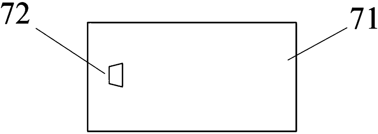
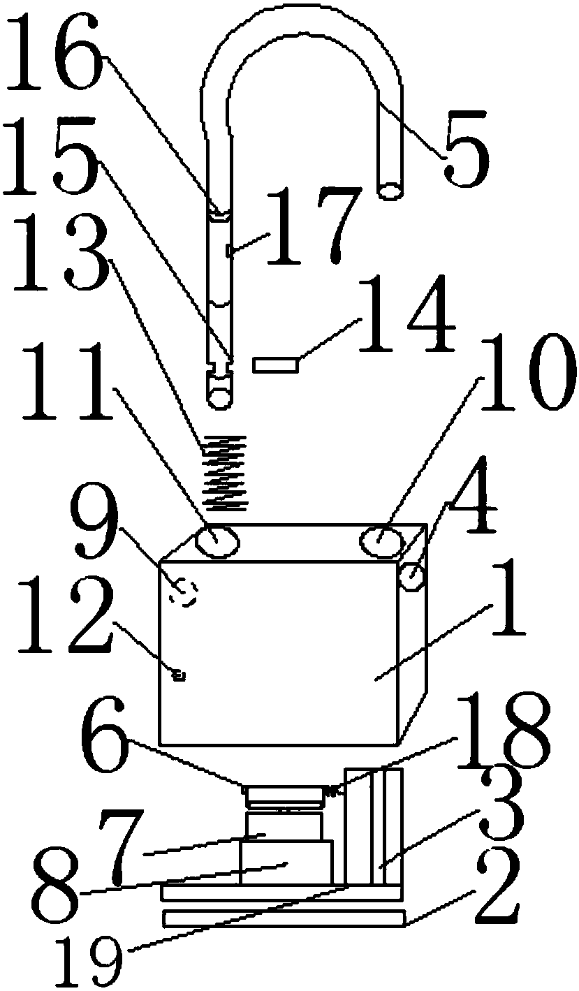
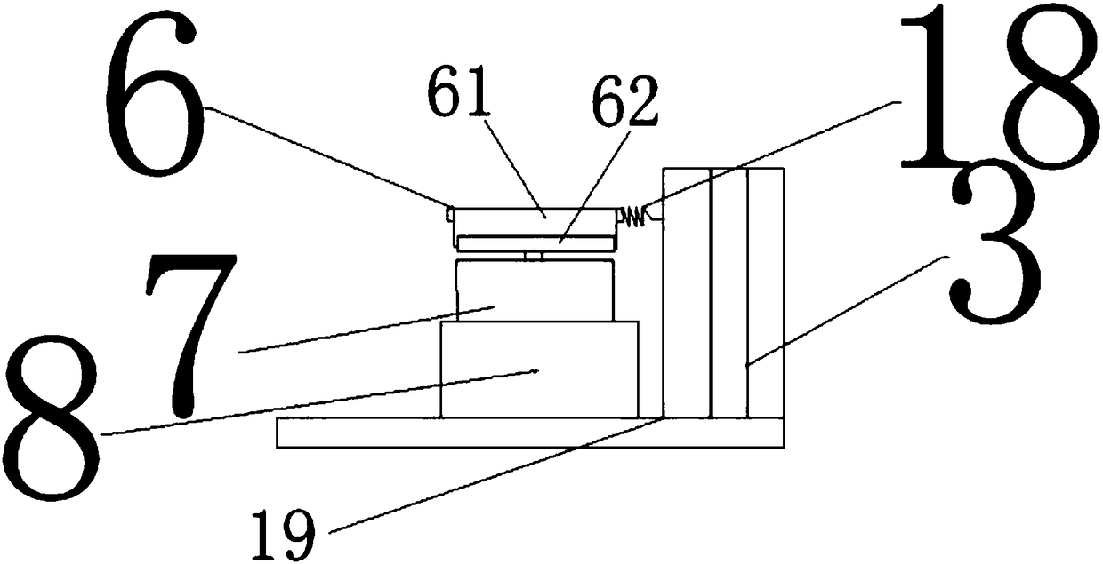

Image

  • Intelligent padlock
  • Intelligent padlock
  • Intelligent padlock

Examples


Embodiment Construction

[0028] It should be noted that, in the case of no conflict, the embodiments of the present invention and the features in the embodiments can be combined with each other.

[0029] In describing the present invention, it should be understood that the terms "center", "longitudinal", "transverse", "upper", "lower", "front", "rear", "left", "right", " The orientations or positional relationships indicated by "vertical", "horizontal", "top", "bottom", "inner" and "outer" are based on the orientations or positional relationships shown in the drawings, and are only for the convenience of describing the present invention and Simplified descriptions, rather than indicating or implying that the device or element referred to must have a particular orientation, be constructed and operate in a particular orientation, and thus should not be construed as limiting the invention. In addition, the terms "first", "second", etc. are used for descriptive purposes only, and should not be understood ...


PUM


Abstract

The invention discloses an intelligent padlock. The padlock includes a lock body and a shackle; the top of the lock body is provided with a first and second lock hole; the lock body is provided with acontrol circuit board, a stepping motor, a reduction gearbox and a mechanical transmission mechanism; the mechanical transmission mechanism includes a transmission block, a second reset spring and alock pin; the long end of the shackle is successively provided with a long strip-shaped latch clamping groove and a locking groove from bottom to top; the second lock hole is provided with a first reset spring; the bottom of the long end of the shackle is in contact with the top of the first reset spring; the side face, on the side of the second lock hole, of the lock body is provided with a latchhole; the long end of the shackle is installed in the second lock hole through a latch, the latch hole and the latch clamping groove; the control circuit board is electrically connected to the stepping motor; the stepping motor is connected to the reduction gearbox; the power output shaft of the reduction gearbox is connected to the transmission block; the transmission block drives the lock pin to insert in or rotate out of the locking groove; the second reset spring is arranged on the end, away from the locking groove, of the transmission block and fixed in the lock body; and the bottom of the lock body is provided with a USB interface. The padlock has no power supply and is not easy to damage; and the convenient changing of shackles with different lengths can be realized.

Description

technical field [0001] The invention belongs to the field of locks, in particular to an intelligent padlock. Background technique [0002] At present, the mechanical locks commonly used in street lamps, substations, and power supply boxes are easily damaged, especially in the wild, where the environmental conditions are harsh and the locks are easily damaged. Now there are some smart padlocks, but these locks require active power supply. The power supply cannot work, and the maintenance is not timely after the lock is broken, which will easily cause great losses. So how to design a kind of indestructible a kind of intelligent padlock becomes the problem demanding prompt solution in this area. Contents of the invention [0003] In view of this, the present invention aims to provide a smart padlock that is not easily damaged. [0004] In order to achieve the above object, technical solution of the present invention is achieved in that way: [0005] An intelligent padlock,...

Claims


Application Information

Patent Timeline
Patent Type & Authority Applications(China)
IPC IPC(8): E05B67/02E05B67/38E05B47/00E05B49/00E05B45/06G07C9/00
CPCE05B67/02E05B45/061E05B47/0012E05B49/00E05B67/38E05B2047/0057G07C9/00174G07C9/00563
Inventor 陶魁达瓦伦珠王建强
Owner 国网西藏电力有限公司拉萨供电公司
Learn More