
A core sampling drilling rig

A technology of core sampling and drilling rigs, which is applied in the direction of rotary drilling rigs, undisturbed core extraction devices, drilling pipes, etc., can solve the problems of lack of equipment, manpower consumption, and harsh working environment, so as to avoid cumbersome manual operations and achieve high automation. Unique effect of structural design

Active Publication Date: 2020-07-28
CHINA NONFERROUS METAL CHANGSHA SURVEY & DESIGN INST CO LTD
View PDF8 Cites 0 Cited by
  • Summary
  • Abstract
  • Description
  • Claims
  • Application Information

AI Technical Summary

Problems solved by technology

However, the fully hydraulic core sampling drilling rigs currently on the market have the defects of low automation and intelligence, and cannot automatically and alternately install or disassemble two or more drill pipes or casings of different sizes during inclined or vertical drilling. Need to rely on manual installation or disassembly one by one
Moreover, the core sampling rig is not fully integrated with functions such as real-time monitoring of the overall situation and the coring process, real-time monitoring of drilling parameters, automatic adjustment of the mast inclination, and remote precise positioning of the rig position information.
In addition, the expansion ability is poor, and the function expansion cannot be directly performed, and the drilling rig cannot be used to realize the online in-situ detection of the rock and soil layer
[0003] In-situ detection is a very important process in the core sampling drilling process. However, none of the core drilling rigs on the market is equipped with a systematic in-situ detection device. Manpower, poor working environment, and potential safety hazards

Method used


Image

  • A core sampling drilling rig
  • A core sampling drilling rig
  • A core sampling drilling rig

Examples


Embodiment 1

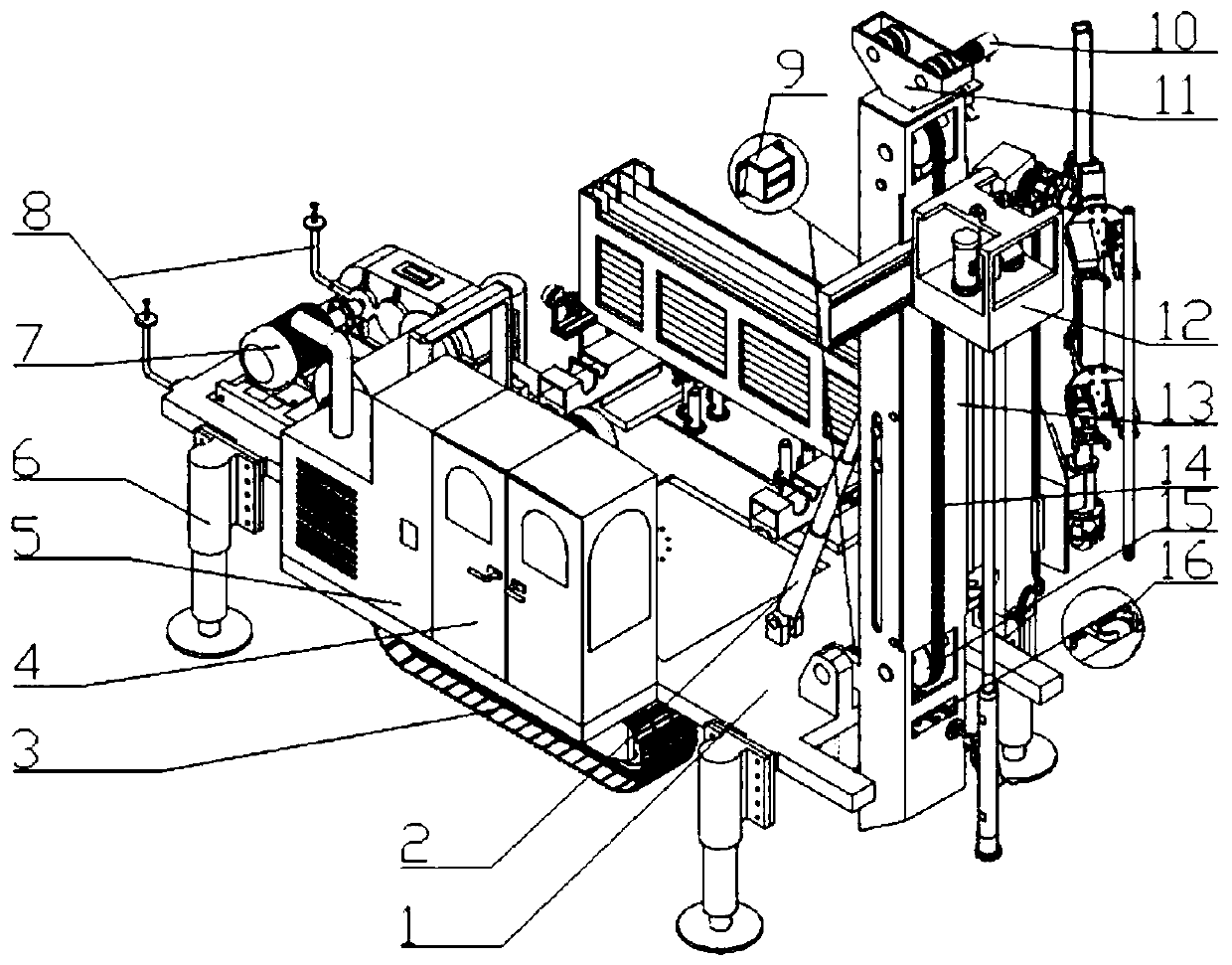
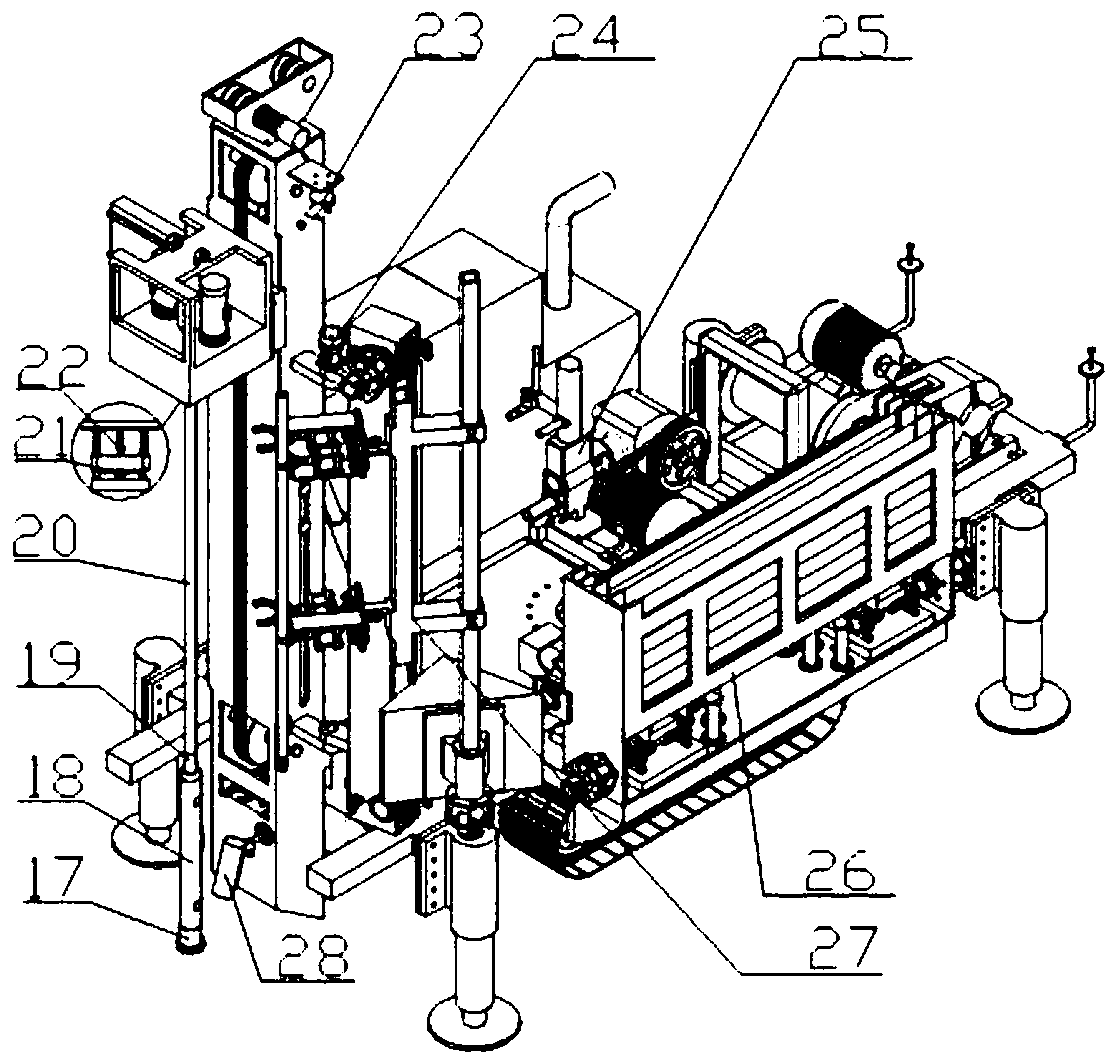
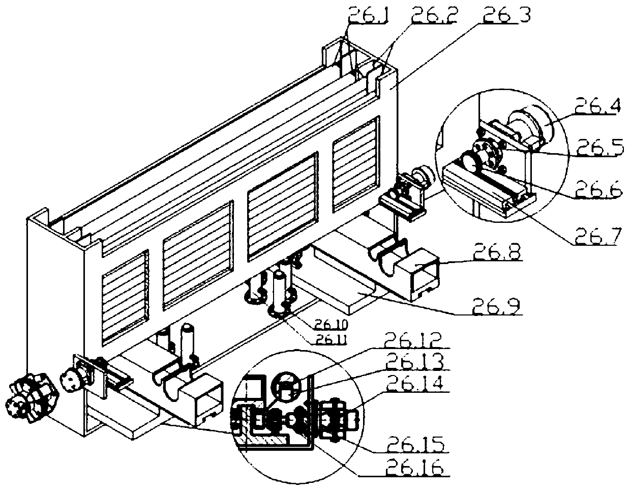
[0040] A core sampling drilling rig, especially an automatic fully hydraulic core drilling rig, including a main frame 1, a mast lifting cylinder 2, a crawler chassis 3, a control room 4, a control cabinet 5, a support leg 6, a hoist assembly 7, and a fixed pulley goose Head 11, power head 12, mast 13, clamping manipulator assembly 16, diamond drill bit 17, core pipe 18, drill pipe 20, mud pump assembly 25, automatic rod feeding mechanism 26 and automatic rod taking mechanism 27, diamond drill bit 17 passes through the core The pipe 18 and the core pipe adapter 19 are arranged on the drill pipe 20, and the drill pipe 20 is arranged on the power head 12, see Figure 1-Figure 5 .

[0041] The crawler chassis 3 and the supporting legs including the supporting legs 6 (hydraulic legs) form a traveling mechanism, which is arranged on the main frame 1 to drive the whole core sampling drilling rig to move.

[0042] Described automatic rod-feeding mechanism 26 sees for details figur...


PUM


Abstract

The invention provides a core sampling drilling rig, which includes a main rack, a walking mechanism, a power head, an automatic rod feeding mechanism and an automatic rod taking mechanism. The automatic rod feeding mechanism includes a storage mechanism, a transporting mechanism and a supporting mechanism, and the automatic taking mechanism includes a lifting mechanism, a grasping spindle attitude transformation mechanism and a manipulator grasping mechanism. According to the technical scheme, the core sampling drilling rig has the effects that structural design of the automatic rod feeding mechanism is ingenious, and automatic transmission of rod pieces with two or more sizes can be realized; structural design of the automatic rod taking mechanism is ingenious, alternate automatic grasping of the rod pieces with two or more different diameters and sizes can be realized, the rod pieces are automatically and additionally installed onto the inclined or vertical power head, or the rod pieces on the power head are disassembled in sequence for recycling, core sampling misering, rotary excavating misering, well drilling or deep hole drilling and other drilling functions can be achievedby simply changing a drilling tool at the tail end; and the degree of automation of the whole core sampling drilling rig is high, automation of core sampling or outer casing pipe loading and unloadingis realized, and tedious manual operation is avoided.

Description

technical field [0001] The invention relates to the field of geological engineering exploration equipment, in particular to a core sampling drilling rig. Background technique [0002] With the continuous development of geological engineering exploration equipment, fully hydraulic core sampling drilling rigs have become the main force of exploration equipment and have made great contributions to the development of geological exploration. However, the fully hydraulic core sampling drilling rigs currently on the market have the defects of low automation and intelligence, and cannot automatically and alternately install or disassemble two or more drill pipes or casings of different sizes during inclined or vertical drilling. It needs to be manually added or disassembled one by one. Moreover, the core sampling rig is not fully integrated with functions such as real-time monitoring of the overall situation and the coring process, real-time monitoring of drilling parameters, autom...

Claims


Application Information

Patent Timeline
Patent Type & Authority Patents(China)
IPC IPC(8): E21B25/00E21B15/00E21B3/02E21B19/14E21B19/18E21B44/00
CPCE21B3/02E21B15/003E21B19/14E21B19/18E21B25/00E21B44/00
Inventor 黄毅李群明周围高志伟
Owner CHINA NONFERROUS METAL CHANGSHA SURVEY & DESIGN INST CO LTD
Learn More