Wire harness terminal automatic measuring instrument

An automatic measurement and wire harness terminal technology, applied in the field of detection and analysis, can solve the problems of coherence and automation, low efficiency, and increased detection cost, and achieve the effect of saving manpower operation costs and improving efficiency

Pending Publication Date: 2019-01-29
广东龙天智能仪器股份有限公司
View PDF0 Cites 0 Cited by
  • Summary
  • Abstract
  • Description
  • Claims
  • Application Information

AI Technical Summary

Problems solved by technology

The equipment that completes the above steps mainly includes: cutting device, grinding device and image acquisition device; however, the existing above-mentioned steps cannot be achieved through a coherent and automated process through one device, but each operation step is completed independently of each other , so the operator must first place the wire harness at the cutting device for cutting, then artificially take the wire harness to the grinding device for grinding, and then clean the wire harness terminal surface by soaking or smearing the liquid to remove the oxide layer, and finally put the The cleaned wiring harness terminal surface is taken to the image acquisition device for image acquisition and analyzed and processed by computer software to determine whether the produced wiring harness terminal pressing condition meets the standards
This approach has the following disadvantages: Since each step is completed, the wire harness needs to be manually moved to the next device for the next step, resulting in increased cost and inefficiency of inspection

Method used


Image

  • Wire harness terminal automatic measuring instrument
  • Wire harness terminal automatic measuring instrument
  • Wire harness terminal automatic measuring instrument

Examples


Embodiment Construction

[0022] In order to describe the technical content, structural features, and achieved effects of the present invention in detail, the following will be described in detail in conjunction with the embodiments and accompanying drawings.

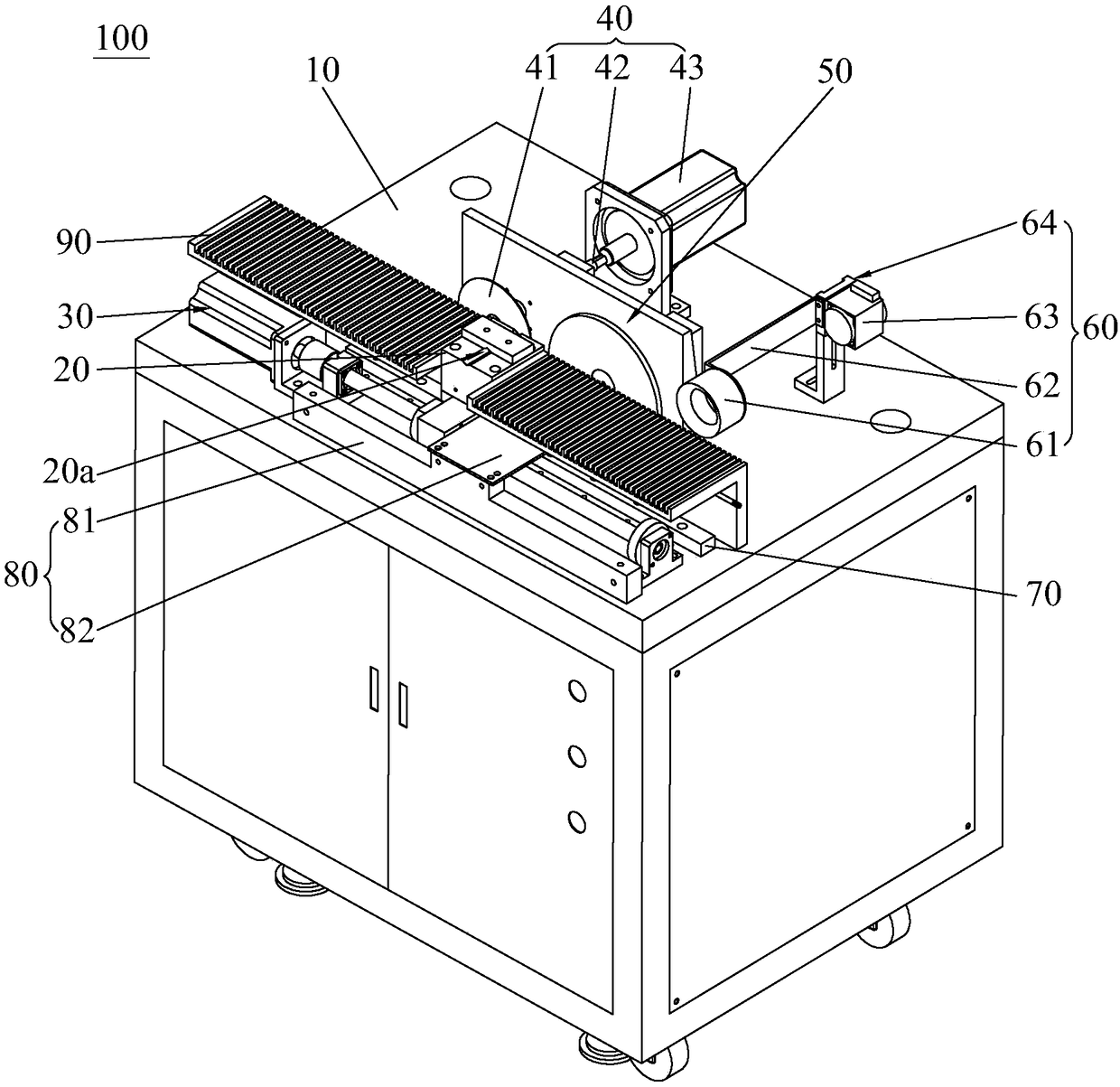
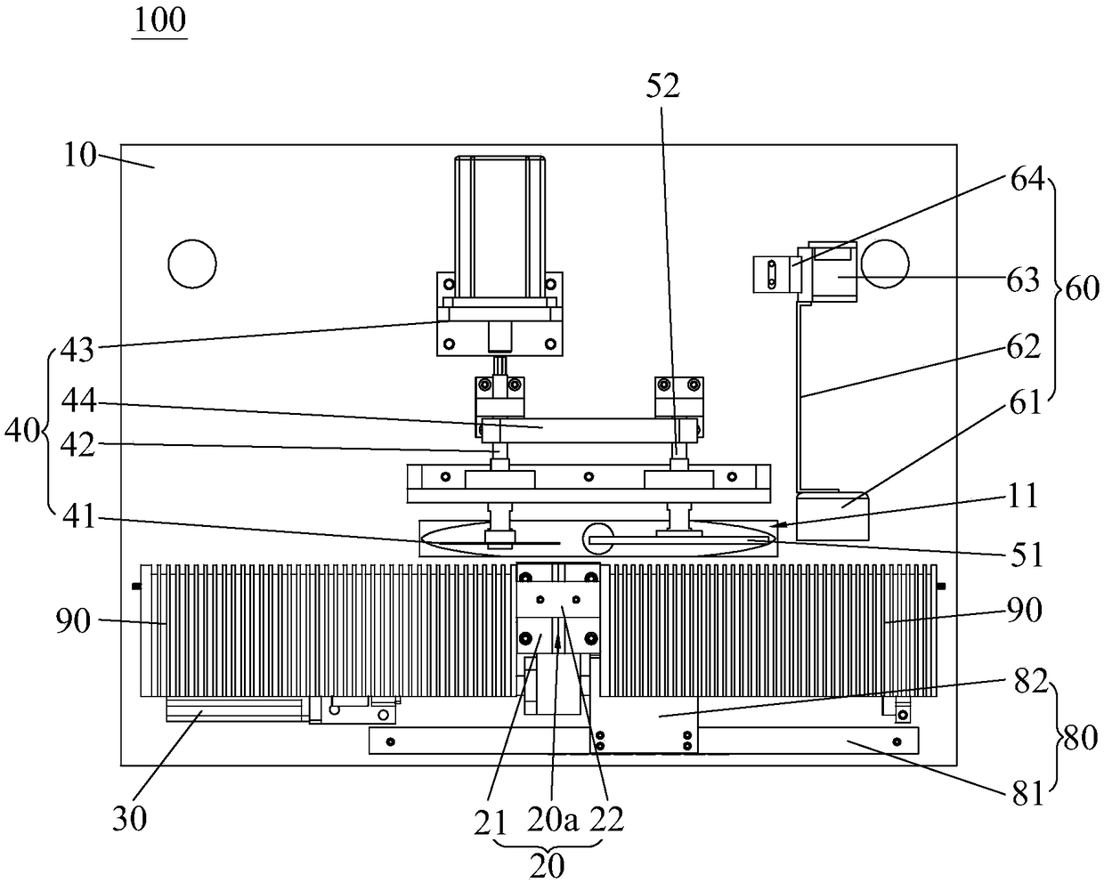
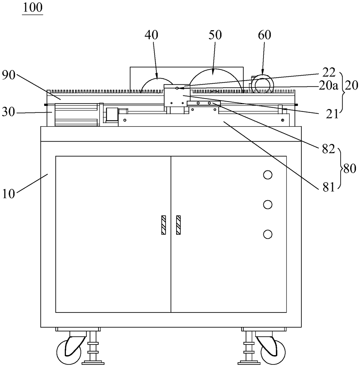
[0023] Please refer to figure 1 and figure 2 The wire harness terminal automatic measuring instrument 100 of the present invention includes a frame 10, a clamp 20 for clamping the wire harness, a driving device 30 for driving the motion of the clamp 20, a cutting device 40 for cutting off terminals exposed outside the wire harness, and a The grinding device 50 for grinding the cross-section of the terminal of the wire harness and the image acquisition device 60 for collecting images of the cross-section of the terminal of the wire harness after grinding. Driving device 30, cutting device 40, grinding device 50 and image acquisition device 60 are all arranged on the frame 10, clamp 20 is connected with the output end of driving device 30, and c...


PUM


Abstract

The invention discloses a wire harness terminal automatic measuring instrument comprising a frame, a clamp used for clamping a wire harness, a drive device used for driving the clamp to move, a cutterused for cutting the terminal exposed outside the wire harness, a polisher used for polishing the section of the terminal of the wire harness, and an image acquisition device used for acquiring images of the polished section of the terminal of the wire harness. The drive device, the cutter, the polisher and the image acquisition device are respectively arranged on the frame; the clamp is connected with the output end of the drive device; the clamp is driven by the drive device to pass the cutter, the polisher and the image acquisition device in order, thus cutting the terminal exposed outsidethe wire harness, polishing the section of the terminal of the wire harness, and acquiring the polished section image of the terminal of the wire harness. The wire harness terminal automatic measuring instrument can realize automatic processes of the cutting, polishing and image acquisition, thus improving the measuring analysis efficiency, and saving labor operation cost.

Description

technical field [0001] The invention relates to the field of detection and analysis, in particular to an automatic measuring instrument for wire harness terminals. Background technique [0002] With the rapid development of society, wire harness is a workpiece used as a connection medium in many fields such as automobiles. In order to ensure the safety of use, it is necessary to measure and analyze the wire harness terminals before the wire harness leaves the factory to judge the quality of the produced wire harness terminals. Whether the pressing condition meets the standard. [0003] The existing process of measuring and analyzing wire harness terminals mainly includes the following steps: cutting the wire harness, grinding the cut wire harness terminals, cleaning the ground surface of the terminals, and image acquisition of the wire harness terminal surface, and then Measure and analyze the collected images. The equipment that completes the above steps mainly includes: ...

Claims


Application Information

Patent Timeline
IPC IPC(8): G01B11/30
CPCG01B11/30
Inventor 李熙龙
Owner 广东龙天智能仪器股份有限公司
Why Eureka
Try Eureka