Coil device

A coil device and coil technology, applied in the direction of transformer/inductor coil/winding/connection, electrical components, transformer/inductor components, etc. The effect of ensuring insulation and ensuring insulation distance

Active Publication Date: 2019-01-29
TDK CORPARATION
View PDF4 Cites 2 Cited by
  • Summary
  • Abstract
  • Description
  • Claims
  • Application Information

AI Technical Summary

Problems solved by technology

For example, in large-scale power transformers used in the field of large-scale solar power generation, since the voltage applied to the coil device becomes high voltage, the required value of the insulation distance expressed by creepage distance and space distance also increases. structure, it is difficult to miniaturize

Method used


Image

  • Coil device
  • Coil device
  • Coil device

Examples


Embodiment Construction

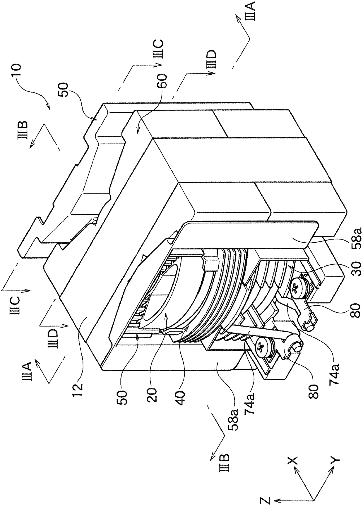
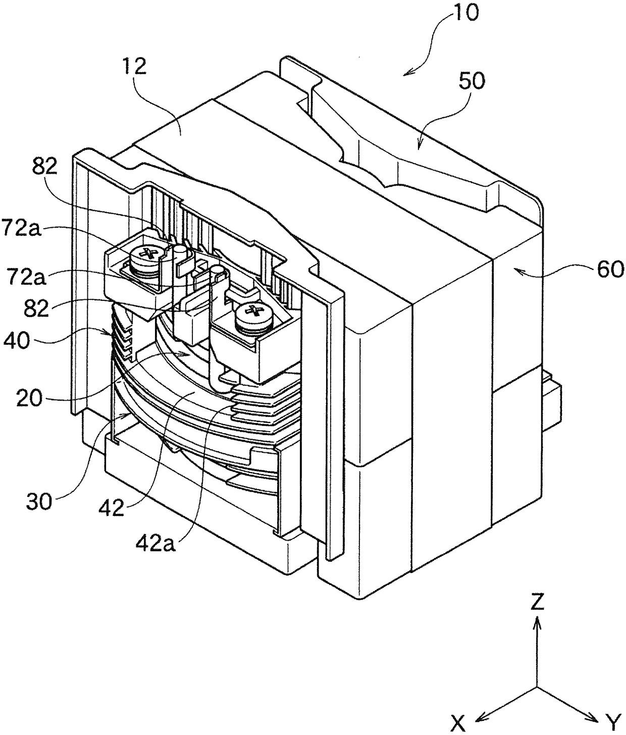
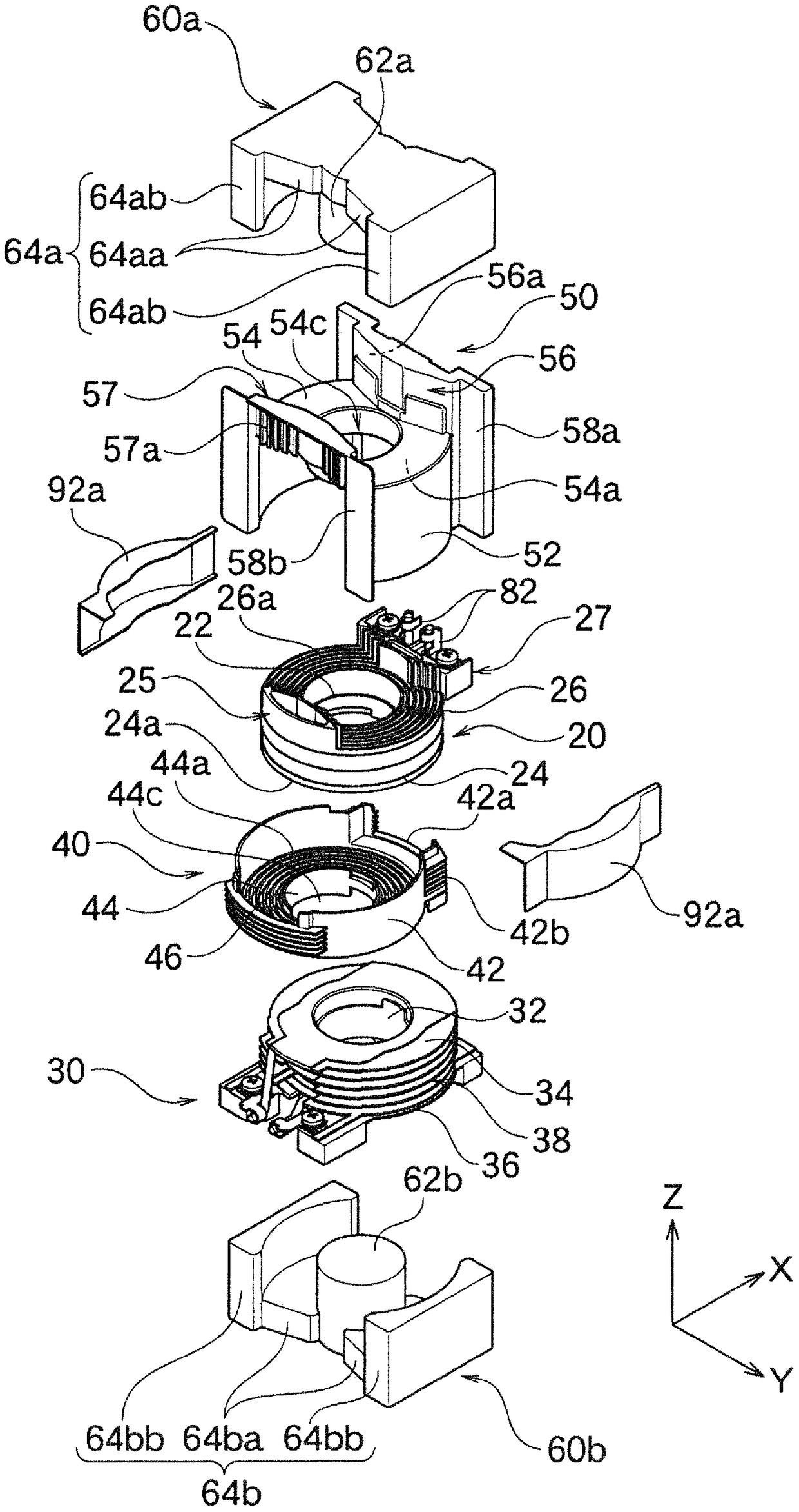
[0085] Figure 1A It is a perspective view of the coil device 10 which concerns on one Embodiment of this invention. The coil device 10 has a first bobbin 20 , a second bobbin 30 , a central cover member 40 , an end cover member 50 , and a core 60 . In addition, the insulating tape 12 is wound on the surface of the core 60 .

[0086] In addition, regarding the coil device 10 according to the embodiment, as Figure 1A As shown, the direction perpendicular to the installation surface on which the coil device 10 is installed is set as the Z-axis direction, and the direction parallel to the installation surface is set as figure 2 The direction connecting the two side leg portions 64ab and 64bb of the core 60 passing through the first frame 20 and the second frame 30 on both sides is referred to as the Y-axis direction, and the direction perpendicular to the Z-axis direction and the Y-axis direction is referred to as The X-axis direction will be described. In addition, the direc...


PUM


Abstract

The invention provides a coil device which can be miniaturized and can properly ensure an insulation characteristic. The coil device (10) is provided with components of a first frame (20) which comprises a first hollow cylinder part (22) that is provided with a first coil (72) that winds at the outer periphery and is hollow and cylindrical, a first end flange part (26) which projects in a direction from one end of the first hollow cylinder part (22) to the profile, and side wall parts (291,292) which project in a direction from the first end flange part (26) to the coiling ribbon of the firstcoil (72) and has wall surfaces that extend from the inner circumference first terminal flange part (26) to the outer circumference; and a core (60a) which is provided with a shaft leg part (62a) thatis inserted into the inner part of the first hollow cylinder part (22), and a connecting part (64a) which passes the outer periphery side of the first frame (20) and is connected with one end of theshaft leg part (62a), wherein at the opposite surfaces (291a,292a) of the side wall parts (291,292), recessed parts and projected parts are formed in a repeated manner from the inner circumference tothe outer circumference of the side wall parts (291,292).

Description

technical field [0001] The present invention relates to a coil device suitably used as a power supply transformer or the like. Background technique [0002] For a coil device used as a transformer or the like, it is necessary to properly ensure insulation between the primary coil and the secondary coil, and between the primary coil and the secondary coil and the core. On the other hand, from the viewpoint of miniaturization of the power supply equipment, downsizing of the coil device included in the power supply equipment is also required. For example, in the large-scale power transformer used in the field of large-scale solar power generation, because the voltage added to the coil device becomes high voltage, the required value of the insulation distance expressed by the creepage distance and the space distance is also increased. structure, it is difficult to achieve miniaturization. [0003] prior art literature [0004] patent documents [0005] Patent Document 1: Jap...

Claims


Application Information

Patent Timeline
Patent Type & Authority Applications(China)
IPC IPC(8): H01F27/02H01F27/24H01F27/28H01F27/29H01F27/30
CPCH01F27/02H01F27/24H01F27/28H01F27/2823H01F27/29H01F27/306
Inventor 春田克己熊谷胜石桥和纪
Owner TDK CORPARATION
Why Eureka
Try Eureka