
PCB spraying device used for electronic products

A technology for PCB boards and electronic products, applied in the field of PCB board spraying devices for electronic products, can solve the problems of poor spraying effect of PCB boards, waste of resources, unfavorable recycling of coatings, etc., to achieve good spraying effect, saving resources, guaranteeing quality effect

Inactive Publication Date: 2019-02-01
郑州莱兹电子科技有限公司
View PDF4 Cites 5 Cited by
  • Summary
  • Abstract
  • Description
  • Claims
  • Application Information

AI Technical Summary

Problems solved by technology

[0004] As an important electronic component, the PCB board is the support of electronic components. The PCB board needs to be sprayed during the production process to prolong the service life of the PCB board. Chinese patent (notification number: CN207770125U) discloses a PCB board Spraying equipment, during the use of this equipment, not only the spraying effect on the PCB board is not good, but also the excess paint is not conducive to recycling during the spraying process, resulting in serious waste of resources

Method used


Image

  • PCB spraying device used for electronic products
  • PCB spraying device used for electronic products
  • PCB spraying device used for electronic products

Examples


Embodiment 1

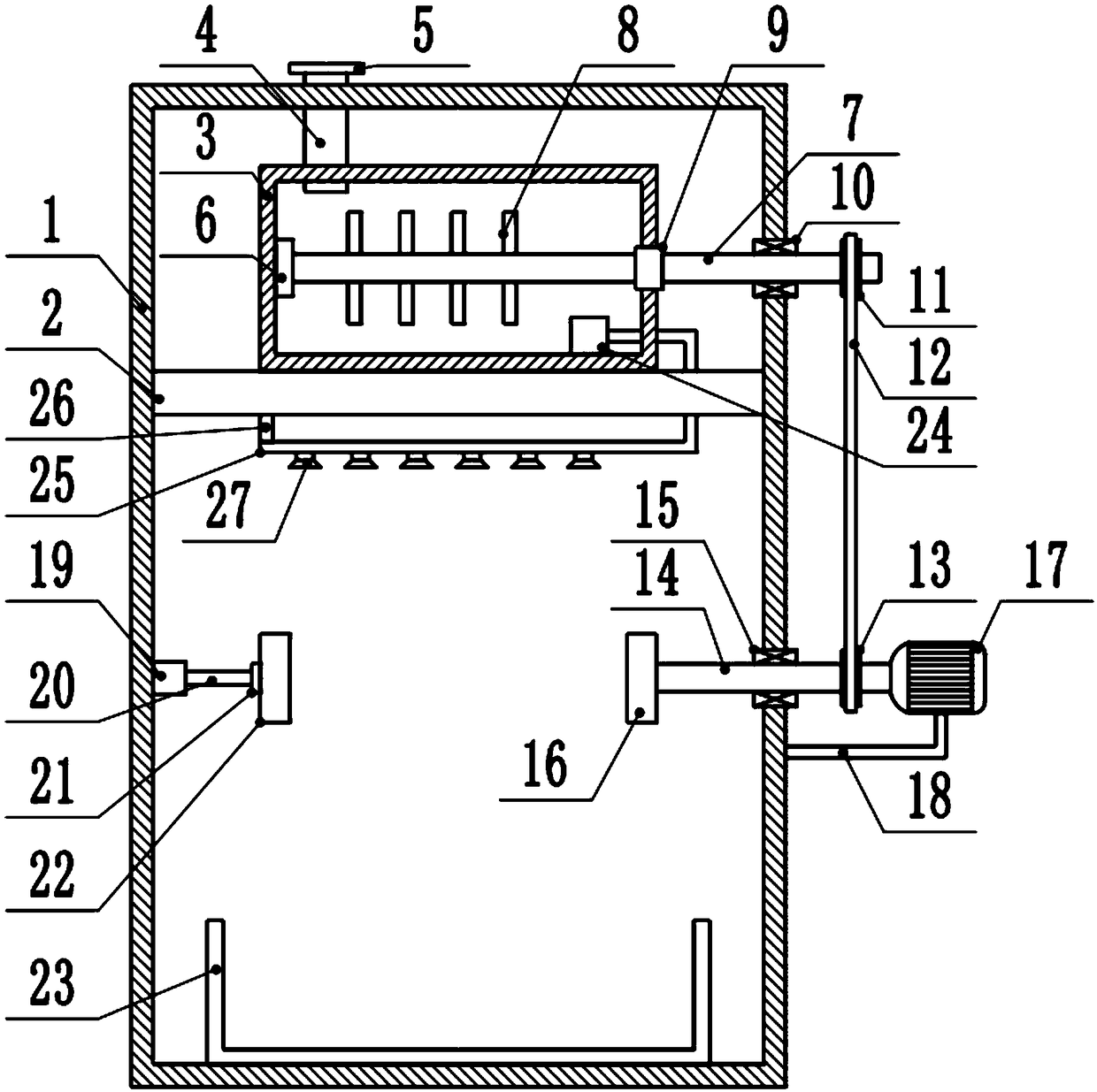
[0021] see Figure 1-2 , a PCB board spraying device for electronic products, including a spraying box 1, a fixed plate 2 is fixedly connected to the top of the box body on the left and right sides inside the spraying box 1, and a mixing box 3 is fixedly installed in the middle of the upper surface of the fixing plate 2, and the mixing box 3. A feed pipe 4 is fixedly connected to the middle of the left side of the upper box to realize feeding the mixing box 3. The upper end of the feed pipe 4 passes through the middle of the left side of the upper box of the spraying box 1. The feed pipe 4 The upper end is equipped with a sealing cover 5, the middle part of the inner wall on the left side of the mixing box 3 is fixedly connected with the first bushing 6, and the middle part of the right side of the first bushing 6 is slidingly connected with the driven rotating rod 7 inside, and the right end of the driven rotating rod 7 passes through The inside of the middle of the box on th...

Embodiment 2

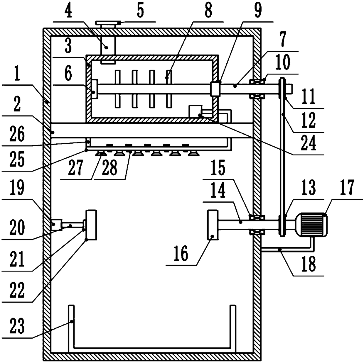
[0024] see image 3 The difference between the second embodiment and the first embodiment is that a control valve 28 is installed in the middle of the left side of the connecting pipe 25, and the control valves 28 are respectively located between the two nozzles 27, and the nozzles are controlled by the control valve 28 for spraying. paint, and control the number of nozzles 27 for spraying according to the length of the PCB board, avoiding simultaneous spraying of all nozzles 27, causing unnecessary waste and saving resources.


PUM


Abstract

The invention discloses a PCB spraying device used for electronic products, and relates to the field of electronic products. The PCB spraying device comprises a spraying box. A fixing plate is fixedlyconnected to the upper portions of the left side and the right side of the interior of the spraying box. A mixing box is fixedly mounted in the middle of the upper surface of the fixing plate. A first shaft sleeve is fixedly connected to the middle of the inner wall of the left side of the spraying box. A driven rotary rod is slidably connected to the interior of the middle of the right side of the first shaft sleeve. The right end of the driven rotary rod penetrates through the interior of the middle of the right side of the mixing box and the interior of the middle of the upper portion of the right side of the spraying box, and an anti-wear sealing rubber pad is connected to the joint of the driven rotary rod and the mixing box in a contact mode. A first bearing is mounted at the jointof the driven rotary rod and the spraying box. By adoption of the PCB spraying device, omnibearing spraying of PCBs can be achieved, and the spraying effect is very good; and in the spraying process,residual paint is collected through a collection box, so that paint is recycled, and resources are saved.

Description

technical field [0001] The invention relates to a relatively large scope, in particular to a PCB board spraying device for electronic products. Background technique [0002] Electronic products are related products based on electric energy, mainly including: watches, smart phones, telephones, televisions, video disc players (VCD, SVCD, DVD), video recorders, camcorders, radios, radio cassette players, combination speakers, CD players (CD), computers, mobile communication products, etc. Because the early products were mainly based on electronic tubes, they were named electronic products. [0003] PCB board, also known as printed circuit board, is the provider of electrical connection for electronic components. Its development has a history of more than 100 years. Its design is mainly layout design. The main advantage of using circuit boards is that it greatly reduces wiring and assembly errors, and improves the automation level and production labor rate. [0004] As an imp...

Claims


Application Information

Patent Timeline
Patent Type & Authority Applications(China)
IPC IPC(8): B05B15/25B05B14/40B05B13/02H05K3/00
CPCB05B13/0228B05B14/40B05B15/25H05K3/0085Y02P70/10
Inventor 张焕
Owner 郑州莱兹电子科技有限公司
Learn More