Automatic treatment equipment used before automobile transmission shaft remanufacturing and transmission shaft treatment technology

An automatic processing and transmission shaft technology, which is applied to the cleaning method using tools, the cleaning method using liquid, the cleaning method and utensils, etc., can solve the problems of low work efficiency, poor cleaning effect, and small use range, and achieve work efficiency. High, thorough cleaning, wide range of effects

Active Publication Date: 2019-02-01
SHANDONG ZHENGYANG MACHINERY CO LTD
View PDF6 Cites 2 Cited by
  • Summary
  • Abstract
  • Description
  • Claims
  • Application Information

AI Technical Summary

Problems solved by technology

[0003] In order to make up for the deficiencies in the prior art, the present invention provides an automatic processing equipment and a transmission shaft treatment process before remanufacturing of the automobile transmission shaft. The present invention can solve the problems of high labor cost and low work efficiency in the cleaning process of the existing automobile transmission shaft , poor cleaning effect, inconvenient adjustment and small use range, etc., it can realize the function of automatic cleaning of automobile drive shaft, with the advantages of low labor cost, high work efficiency, good cleaning effect, good adjustability and wide use range, etc.

Method used


Image

  • Automatic treatment equipment used before automobile transmission shaft remanufacturing and transmission shaft treatment technology
  • Automatic treatment equipment used before automobile transmission shaft remanufacturing and transmission shaft treatment technology
  • Automatic treatment equipment used before automobile transmission shaft remanufacturing and transmission shaft treatment technology

Examples


Embodiment Construction

[0023] In order to make the technical means, creative features, goals and effects achieved by the present invention easy to understand, the present invention will be further described below in conjunction with specific illustrations.

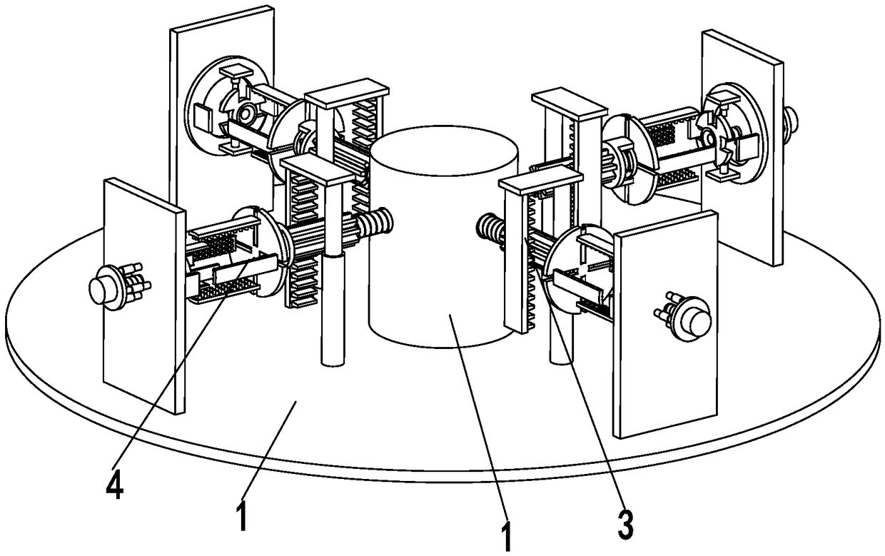
[0024] Such as Figure 1 to Figure 6 As shown, an automatic processing equipment before remanufacturing of an automobile drive shaft includes a bottom plate 1, a mounting column 2, a cleaning device 3 and a clamping device 4. The middle part of the bottom plate 1 is equipped with a mounting column 2, and the mounting column 2 is a cylindrical structure. , the side wall of the mounting column 2 is uniformly provided with mounting holes along its circumferential direction, a cleaning device 3 is installed in the mounting hole, and a clamping device 4 is arranged on the outside of the cleaning device 3, and the clamping device 4 is installed on the bottom plate 1; wherein:

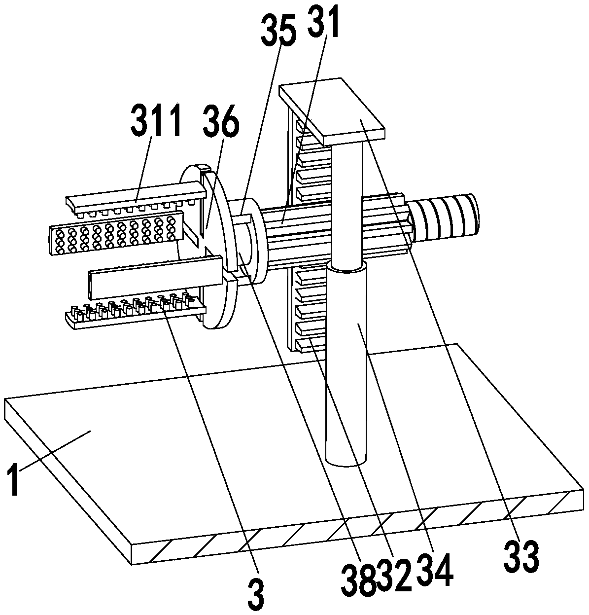
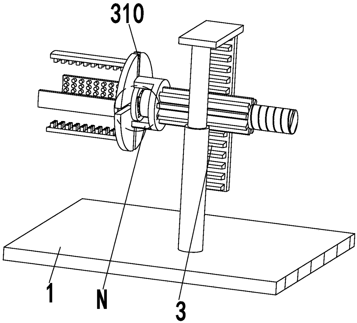
[0025]The cleaning device 3 includes a push rod 31, a push rack 32, a conn...


PUM


Abstract

The invention relates to automatic treatment equipment used before automobile transmission shaft remanufacturing and a transmission shaft treatment technology. The automatic treatment equipment comprises a bottom plate, an installing column, cleaning devices and clamping devices. The installing column is arranged at the middle portion of the bottom plate and is of a cylinder structure. Installingholes are evenly formed in the side wall of the installing column in the circumferential direction of the installing column. The cleaning devices are arranged in the installing holes. The clamping devices are arranged on the outer sides of the cleaning devices. The clamping devices are arranged on the bottom plate. Each cleaning device comprises a pushing rod, a pushing rack, a connecting plate, apushing air cylinder, an installing frame, a fixing panel, an adjusting panel, an adjusting motor, protruding columns, an adjusting rod and an outer wall cleaning brush. The automatic treatment equipment and the transmission shaft treatment technology can solve the problems that in the existing automobile transmission shaft cleaning process, the labor cost is high, the work efficiency is low, thecleaning effect is poor, adjusting is not convenient, and the usage range is narrow; and the function of automatic cleaning of automobile transmission shafts can be achieved, and the advantages thatthe labor cost is low, the work efficiency is high, the cleaning effect is good, adjustability is good, and the usage range is wide are achieved.

Description

technical field [0001] The invention relates to the field of cleaning equipment for automobile parts, in particular to an automatic processing equipment before remanufacturing of an automobile transmission shaft and a processing technology for the transmission shaft. Background technique [0002] Remanufacturing refers to the mass production process of professionally repairing waste auto parts, engineering machinery, machine tools, etc. The remanufactured products achieve the same quality and performance as the original new products, which is an advanced form of "reuse" in circular economy. Focusing on the remanufacturing of automobile engines, gearboxes, generators and other parts, my country has expanded the scope of pilot remanufacturing of auto parts to include transmission shafts, oil pumps, water pumps and other components. Among them, before remanufacturing the automobile transmission shaft, the transmission shaft must be cleaned. The cleanliness of the cleaning is ve...

Claims


Application Information

Patent Timeline
Patent Type & Authority Applications(China)
IPC IPC(8): B08B1/02B08B3/08B08B3/02B08B13/00
CPCB08B1/002B08B1/02B08B1/04B08B3/02B08B3/08B08B13/00
Inventor 方志兰
Owner SHANDONG ZHENGYANG MACHINERY CO LTD
Why Eureka
Try Eureka