

Split roller transverse movement device with oil-gas quick connection function
A traverse device and split technology, applied in metal rolling, manufacturing tools, metal rolling, etc., can solve the problems of inconvenient maintenance, complex structure, occupying maintenance and operation space, etc., and achieve easy maintenance and operation. Compact structure, easy to retrofit
- Summary
- Abstract
- Description
- Claims
- Application Information
AI Technical Summary
Problems solved by technology
Method used
Image

Examples
Embodiment 1
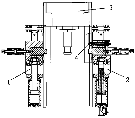
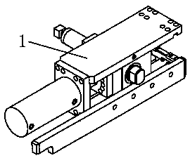
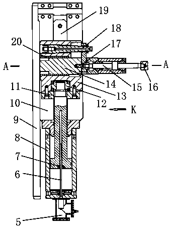
[0025] A split roll traversing device with an oil-gas quick connection function, including a roll chock 3 on which a male joint 4 is mounted, and left traversing frames 1 and 1 on both sides of the roll chock 3 respectively. Right traversing frame 2, described right traversing frame 2 and left traversing frame 1 are equipped with traversing oil cylinder 8, the cylinder bottom of described traversing oil cylinder 8 is connected with magnetic ruler 6, and described traversing oil cylinder 8 A magnetic ring 7 is set on the piston of the traversing cylinder 8, a cylinder head 12 is connected to the traversing cylinder 8, and the top of the piston rod of the traversing cylinder 8 is installed in the slider 13, and the slider 13 has a mounting groove One, the top and bottom of the slider 13 are respectively connected to the upper platen 21 and the lower platen 10 by bolts, the bottom of the upper platen 21 is provided with a mounting hole 1, and the inner side of the mounting hole 1 ...
Embodiment 2
[0027] On the basis of Embodiment 1, the cylinder head 12 is installed on the inner side wall of the installation groove one, and a baffle plate 11 is installed on one side of the installation groove one, and the baffle plate 11 can play a position-limiting role, so that To achieve the normal operation of the device.
Embodiment 3
[0029] On the basis of Embodiment 1 or 2, the top and bottom of the slider 13 are provided with two installation grooves, and the two installation grooves are respectively sleeved on one end of the upper guide key 22 and the lower guide key 19, so that the slider 13 guiding action.
PUM
 Abstract
Description
Claims
Application Information