Numerical control corner cutting and edge folding machine equipment

A technology of edge folding machine and corner cutting, applied in metal processing equipment, feeding device, positioning device, etc., can solve the problems of many turnover links, large size deviation, strain, etc., save manpower and material resources, simple and convenient operation, The effect of saving mold cost

Inactive Publication Date: 2019-02-01
优尔屋面科技(苏州)有限公司
View PDF0 Cites 2 Cited by
  • Summary
  • Abstract
  • Description
  • Claims
  • Application Information

AI Technical Summary

Problems solved by technology

[0002] The existing technology requires the use of corner cutting equipment, manual bending machines, and special bending for small-angle extrusion. The CNC bending machine can be completed in multiple lanes, occupying space, equipment, and personnel, and there are many turnover links, and the folding method is used. , the surface of the material is prone to creases, strains, etc., and multiple processes are likely to cause large dimensional deviations, etc.; the CNC corner cutting and edge folding machine equipment is now designed so that all processes can be completed on one device

Method used


Image

  • Numerical control corner cutting and edge folding machine equipment
  • Numerical control corner cutting and edge folding machine equipment
  • Numerical control corner cutting and edge folding machine equipment

Examples


Embodiment Construction

[0021] The present invention is described in detail below in conjunction with accompanying drawing and specific embodiment:

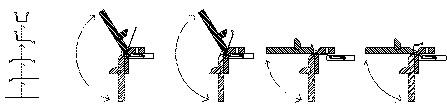
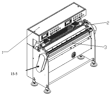
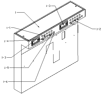
[0022] Such as Figure 1 to Figure 4 As shown, a numerically controlled corner cutting and folding machine equipment is characterized in that it includes a numerical control system electrical cabinet 1, a numerically controlled cylinder corner cutting device 2, and a numerically controlled corner folding machine device 3. The scratched brush table top 4 is also provided with a numerical control cylinder corner cutting device 5 on both sides of the brush table top 4, and a first linear screw module 6 is installed next to the numerical control cylinder corner cutting device 5, and the first linear screw The module 6 is equipped with a cylinder induction clamping slide table 7, and the CNC folding machine equipment 3 includes a main frame 8 of the folding machine, and the rear side of the main frame 8 of the folding machine is provided with a gear position...


PUM


Abstract

The invention relates to the field of mechanical automation, in particular to numerical control corner cutting and edge folding machine equipment. The numerical control corner cutting and edge foldingmachine equipment comprises a numerical control system electric appliance cabinet, numerical control air cylinder corner cutting equipment and numerical control edge folding machine equipment. The numerical control air cylinder corner cutting equipment comprises a brush tabletop capable of avoiding material surface scratching. Numerical control air cylinder corner cutting devices are further arranged on the two sides of the brush tabletop. A first linear lead screw module is arranged beside each numerical control air cylinder corner cutting device and provided with an air cylinder induction clamping sliding table. A numerical control edge folding machine comprises an edge folding machine main rack. The rear side of the edge folding machine main rack is provided with an edge folding machine lifting rear gear. Edge folding upper pressing plate lifting lead screw motors are arranged on the two sides of the edge folding machine main rack. An edge folding overturning plate speed reducer isarranged below the edge folding machine main rack. The numerical control corner cutting and edge folding machine equipment has the beneficial effects that a corner cutting machine and the edge folding machine are combined, operation is simple and convenient, manpower and material resources are saved, material surface pulling damage cannot be caused during remanufacturing, die folding marks are avoided, meanwhile, special dies are not needed for small-angle edge folding, and the die cost is saved.

Description

technical field [0001] The invention relates to the field of mechanical automation, in particular to a numerically controlled corner-cutting and edge-folding machine. Background technique [0002] In the existing technology, corner cutting equipment, manual bending machine, and special bending forming for small-angle extrusion are required. The CNC bending machine can be completed in multiple channels, occupying space, equipment, and personnel, and there are many turnover links, and the folding method is used. , The surface of the material is prone to creases, strains, etc., and multiple processes are likely to cause large dimensional deviations, etc.; the CNC corner cutting and edge folding machine equipment is now designed so that all processes can be completed on one device. Contents of the invention [0003] The technical problem to be solved by the present invention is to provide a numerically controlled corner cutting and folding machine equipment, which will not cau...

Claims


Application Information

Patent Timeline
IPC IPC(8): B21D19/08B21D43/28
CPCB21D19/08B21D43/28
Inventor 邹志强
Owner 优尔屋面科技(苏州)有限公司
Why Eureka
Try Eureka