
A circuit board cutting equipment based on dust absorption principle

A dust absorption and cutting equipment technology, applied in metal processing and other directions, can solve the problems of high temperature, humidity and dust requirements, and the influence of circuit board use, so as to achieve better blowing effect, improve filtering effect, and increase flow rate.

Active Publication Date: 2020-06-12
吴江南联电子有限公司
View PDF7 Cites 0 Cited by
  • Summary
  • Abstract
  • Description
  • Claims
  • Application Information

AI Technical Summary

Problems solved by technology

[0004] Chinese patent (CN202037628U) is a printed circuit board cutting device, which specifically discloses a cutting method for circuit boards. However, the circuit board cutting machine will generate some dust during the process of cutting circuit boards. Precision components have high requirements on temperature, humidity and dust. Obviously, if this part of dust falls on the circuit board, it will have a great impact on the use of the circuit board.

Method used


Image

  • A circuit board cutting equipment based on dust absorption principle
  • A circuit board cutting equipment based on dust absorption principle
  • A circuit board cutting equipment based on dust absorption principle

Examples


Embodiment 1

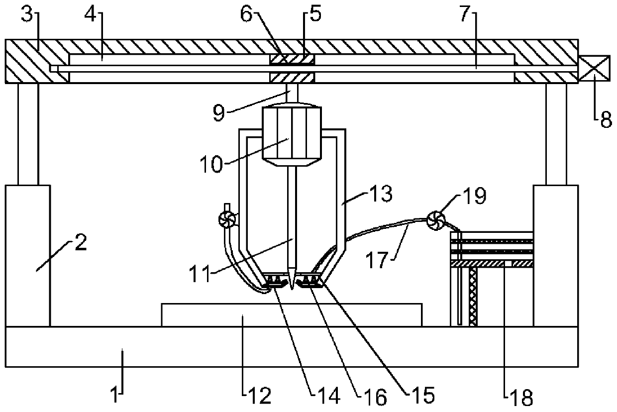
[0024] see figure 1 , in an embodiment of the present invention, a circuit board cutting device based on the principle of dust absorption, including a base plate 1, a circuit board 12 is placed on the base plate 1, two electric push rods 2 are fixedly connected to the left and right ends of the base plate 1, two The top of the electric push rod 2 is jointly fixedly connected with a top plate 3, and the top plate 3 is provided with a moving groove 4 with the opening facing downwards. A moving block 5 is arranged in the moving groove 4, and a threaded through hole 6 is provided on the moving block 5. The hole 6 is internally threaded with a threaded rod 7, the two ends of the threaded rod 7 are rotationally connected with the two ends of the moving groove 4, and the right end of the threaded rod 7 is fixedly connected with the output shaft of the motor 8, and the lower side of the moving block 5 is fixedly connected through the connecting column 9 Cutting motor 10 is arranged, a...

Embodiment 2

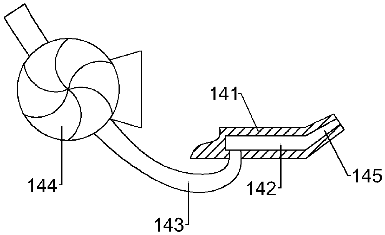
[0027] see figure 1 and figure 2 , the outer cover of the cutting motor 10 is provided with a protective cover 13, and the outer bottom of the protective cover 13 is provided with a blowing device 14, and the blowing device 14 includes an air distribution ring plate 141, and the air distribution ring plate 141 is fixedly connected with the bottom end of the protective cover 13 , and the inside of the air distribution ring plate 141 is provided with an air distribution cavity 142, the air distribution cavity 142 is connected to the blower 144 on the outer wall of the protective cover 13 through the first hose 143, and the inner side of the air distribution ring plate 141 is fixedly connected There is a raised part 145, which will produce a little dust during cutting. At this time, start the blower 144, and the blower 144 will blow the outside air into the air distribution chamber 142 through the first hose 143, and then spray it out through the raised part 145, so that The du...

Embodiment 3

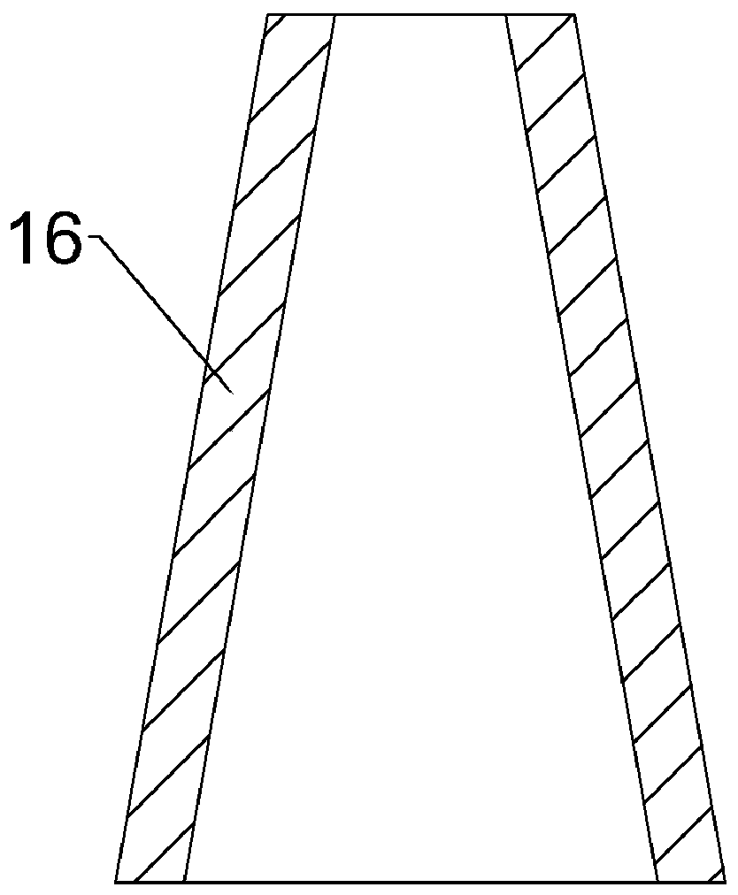
[0030] see figure 1 and image 3 , the inner bottom of the protective cover 13 is fixedly connected with an absorbing ring plate 15, and an absorbing cavity is opened inside the absorbing ring plate 15, and several absorbers 16 are evenly arranged on the lower side of the absorbing ring plate 15, and the cross section of the absorbing bodies 16 is It is in the shape of an isosceles trapezoid with a small top and a large bottom, and the absorber 16 communicates with the inside of the absorbing cavity. The absorbing ring plate 16 communicates with the absorbing device 18 on the bottom plate 1 through the second hose 17, and the second hose 17 is provided with an induced fan 19, and the induced fan 19 works to suck the dust entering the protective cover 13 into the absorption cavity through the absorber 16, and then enters the absorption device 18 through the second hose 17 to be absorbed;


PUM


Abstract

The invention provides circuit board cutting equipment based on a dust adsorption principle. The circuit board cutting equipment comprises a baseplate, wherein a circuit board is placed on the baseplate; two electric push rods are fixedly connected with the left and right ends of the baseplate; a top plate is fixedly connected with the top ends of the electric push rods jointly; a moving groove ofwhich the opening faces down is formed in the top plate; a moving block is arranged in the moving groove; a threaded through hole is formed in the moving block; a threaded rod is in threaded connection with the interior of the threaded through hole; two ends of the threaded rod are rotationally connected with two ends of the moving groove; the right end of the threaded rod is fixedly connected with an output shaft of a motor; a cutting motor is fixedly connected with the lower side of the moving block through a connecting column; a cutter is fixedly connected onto an output shaft of the cutting motor; and a protective hood is arranged on the outer side of the cutting motor in a covering manner. The circuit board cutting equipment provided by the invention has the following beneficial effects: outside air is blown by an air blower into an air distribution cavity through a first hose, and the blown air is jetted through a warped part, so that dust can move up, can enter the protective hood, and can be prevented from falling onto the circuit board.

Description

technical field [0001] The invention relates to the technical field of circuit boards, in particular to a circuit board cutting device based on the principle of dust absorption. Background technique [0002] A circuit board refers to a device made by utilizing and controlling the laws of electronic motion in a vacuum, gas or solid. Divided into electric vacuum devices, gas-filled tube devices and solid-state circuit boards. In the analog current, it is used for rectification, amplification, modulation, oscillation, frequency conversion, phase locking, control, correlation, etc.; in the digital current, it is used for sampling, limiting, logic, storage, counting, delay, etc. The gas-filled tube device is mainly used for rectification , Voltage stabilization and display purposes, solid-state circuit boards such as integrated current. [0003] The circuit board cutting machine can cut and disconnect the circuit board, and can also perform "V" groove cutting on the circuit boa...

Claims


Application Information

Patent Timeline
Patent Type & Authority Patents(China)
IPC IPC(8): B26D7/18
CPCB26D7/1854B26D7/1863
Inventor 李欣
Owner 吴江南联电子有限公司
Learn More