Oil-gas separation system with secondary separation function

A separation system and secondary separation technology, applied in the direction of engine components, machines/engines, mechanical equipment, etc., can solve the problems of large space occupation, inability to compress the number of filter elements, poor deceleration effect of the impact channel, etc., to reduce deformation, improve oil and gas Separation effect, effect of reducing impact pressure

Inactive Publication Date: 2019-02-01
SHENTONG TECH GRP CO LTD
View PDF1 Cites 4 Cited by
  • Summary
  • Abstract
  • Description
  • Claims
  • Application Information

AI Technical Summary

Problems solved by technology

In practical applications, the impact channel of the oil-containing airflow in this type of oil-gas separation device is long and takes up a lot of space. It is difficult to miniaturize and lighten the engine, which affects the layout of the engine compartment; the deceleration effect of the impact channel is poor, and the impact on the filter components is large. As a result, the filter element is easily deformed and affects the filtering effect, so the number of filter elements cannot be compressed, and there is no advantage in cost

Method used


Image

  • Oil-gas separation system with secondary separation function
  • Oil-gas separation system with secondary separation function
  • Oil-gas separation system with secondary separation function

Examples


Embodiment Construction

[0021] The present invention will be further described below in conjunction with the drawings and specific embodiments.

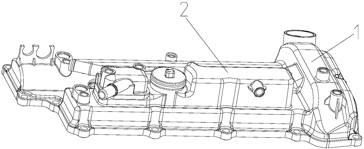
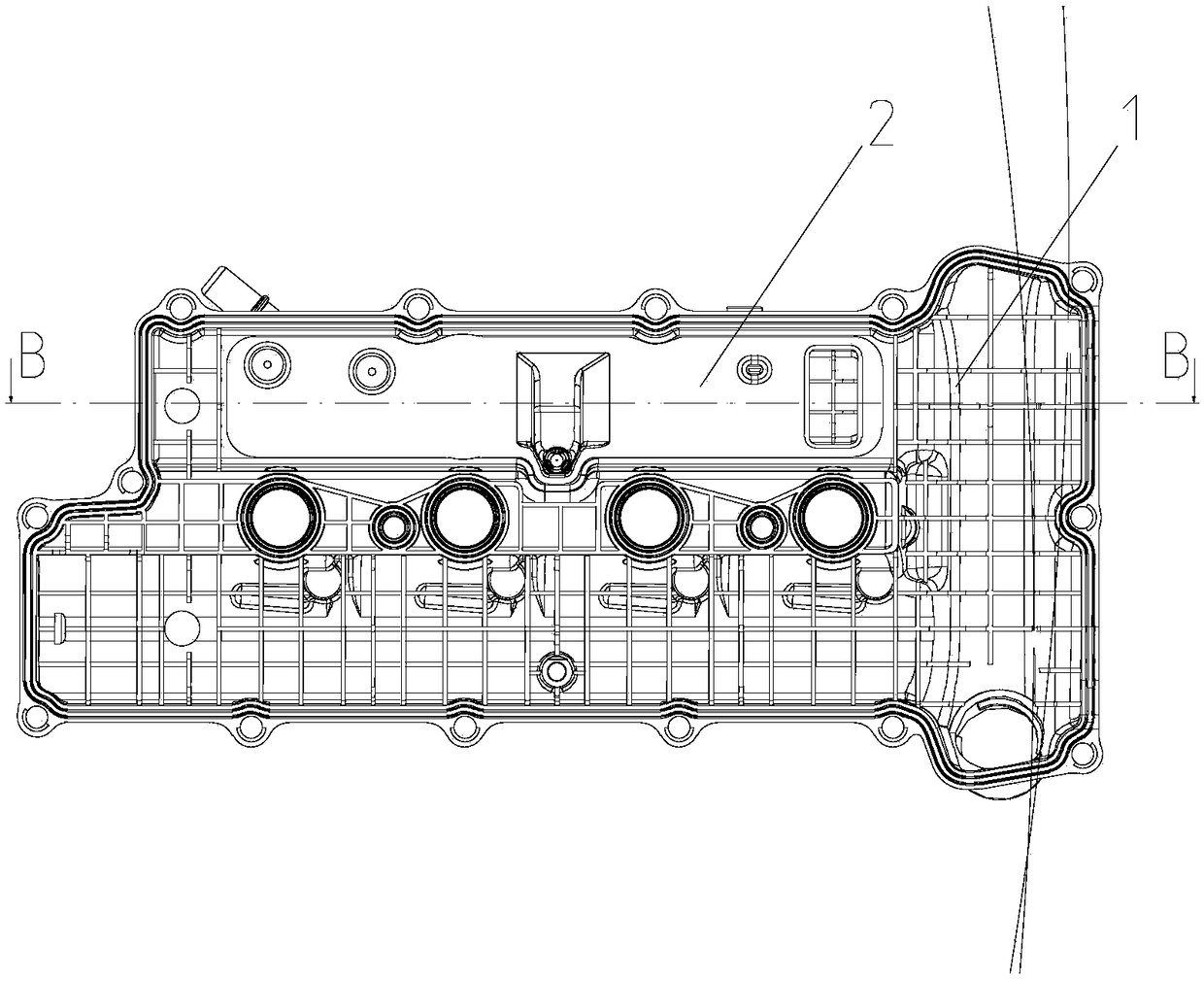
[0022] Such as figure 1 , figure 2 , image 3 The illustrated embodiment is a secondary separation oil and gas separation system, which is mainly used to separate oil and gas from the gas mixed with oil from the engine.

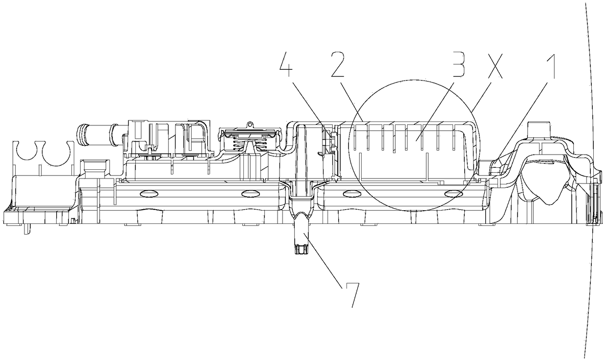
[0023] The separation system of this example includes a cylinder cover body 1, a cover 2 is provided on the cylinder cover body, a coarse separation structure 3 and a fine separation structure 4 are provided on the oil and gas circuit under the cover, and the coarse separation structure is located on the upstream side. The fine separation structure is located on the downstream side.

[0024] Such as Figure 4 As shown, the coarse separation structure includes a labyrinth air passage 3 arranged on the oil and gas circuit, and several labyrinth air passage retaining walls 8 are provided in the labyrinth air passage. A number of airflow decelerati...


PUM


Abstract

The invention discloses an oil-gas separation system with a secondary separation function. The oil-gas separation system with the secondary separation function comprises an oil-gas loop arranged on acylinder cover hood, the oil-gas loop is provided with a coarse separation structure and a fine separation structure, and the coarse separation structure is located on the upstream side of the fine separation structure. The coarse separation structure comprises a labyrinth air path arranged on the oil-gas loop. The fine separation structure comprises a fine separator shell and filter cotton. The shape of the fine separator is matched with the shape of the section of the oil-gas loop, and the fine separator shell is provided with a mounting structure capable of being fixed to the oil-gas loop.The oil-gas separation system is further provided with a baffle, the baffle is parallel to the mounting side of the filter cotton of the fine separator shell and is relatively fixed to the fine separator shell. The filter cotton is fixed to the baffle side between the baffle and the fine separator shell. A plurality of oil-gas separation holes are formed in the position, corresponding to the filter cotton, of the fine separator shell correspondingly in a penetrating mode. The oil-gas separation system with the secondary separation function has the beneficial effects that the impact pressure ofgas containing oil is sufficiently weakened, the degree of deformation of a filter element is reduced, and the optimal oil-gas separation effect can be ensured.

Description

Technical field [0001] The invention relates to the field of engines, in particular to a secondary separation oil and gas separation system. Background technique [0002] Chinese patent document CN207686788U published on August 3, 2018 the "engine oil and gas separation structure", which includes a cylinder head cover and an oil baffle plate. The cylinder head cover is provided with a labyrinth air passage. The oil plate is provided with a filter baffle group, which includes a filter I, a wave baffle and a baffle I. The wave baffle and baffle I are fixedly connected, and the filter I, wave baffle and baffle The plates I are fixedly connected to the oil baffle plate. The oil baffle plate is also provided with an air intake frame body. The side of the air intake frame body and the oil baffle plate is provided with a through hole I. The through hole I corresponds to the air inlet hole; the air inlet on the side away from the filter baffle group The side of the frame body is provid...

Claims


Application Information

Patent Timeline
Patent Type & Authority Applications(China)
IPC IPC(8): F01M13/04
CPCF01M13/04F01M2013/0438F01M2013/0461
Inventor 方立锋蔡炳芳饶聪超成宇
Owner SHENTONG TECH GRP CO LTD
Why Eureka
Try Eureka